Block hoist

a hoist and block technology, applied in the field of block hoists, can solve the problems of difficulty in moving large logs toward the splitter, inability to move large logs into close proximity with the hydraulic cylinder and wedge, and inability to handle firewood indoors, etc., to achieve the effect of facilitating lifting, maneuvering, positioning

Inactive Publication Date: 2006-03-14
PETERSON BYRON
View PDF21 Cites 18 Cited by
  • Summary
  • Abstract
  • Description
  • Claims
  • Application Information

AI Technical Summary

Benefits of technology

[0013]The invention comprises a block hoist system fit onto conventional hydraulic splitter units to assist in the lifting, maneuvering, and positioning of large logs that require multiple radial splits to section them for firewood. In a first embodiment, the block hoist comprises a lifting cable and pulley system cooperatively linking the upward, hydraulically-powered movement of the ram and splitting wedge with the lifting of a log section connected to the lift cable by an auger or dog and an adjustable chain. The dog (or other securing device) is pounded securely into the log section, preferably near the center, and attached by an adjustable chain section to the cable and pulley system. As the hydraulically-powered ram and wedge is raised into its upward position (at the commencement of splitting and between splits), the inventive cable and pulley system fitted to the unit's I-beam guide structure lift the chain and auger, thereby pulling and lifting the log. Once the log is partially or fully lifted, the person operating the unit may easily swing the log into position between the wedge and foot plate and rotate the log, as needed, between splits.

Problems solved by technology

Larger logs up to about 30–40″ in diameter can be split using these units; however they pose several problems given their weight and dimensions.
First, moving larger, heavier logs toward the splitter and into close proximity with the hydraulic cylinder and wedge is difficult, particularly if there is only one person using the unit.
If the log has to be moved on the ground, one or more sides of the log may become covered in dirt or mud which makes the resulting firewood undesirable for indoor handling.
Second, large logs (i.e., from 12 up to 40 inches in diameter) are difficult to position on the foot plate of a vertically-oriented hydraulic unit, as the foot plate is sized for placement of logs of approximately 10″ in diameter.
As a result, the larger log cannot be centered over the foot plate.
If the log is tipped at an angle when resting on the foot plate, the hydraulically-powered wedge will contact the log at an angle resulting in uneven and unpredictable splits in the log, which can be dangerous.
Third, large logs are difficult to manipulate once the splitting has commenced.
This maneuvering by hand of a heavy, partially split or fractured log is time consuming and often requires that the larger log be completely rotated out of position off of the foot plate and re-positioned back onto the foot plate.
In sum, even with the advantages of a hydraulic splitting unit, such units are not designed to handle large logs.
Splitting large logs requires significant back and arm strength, and time-consuming effort in: (1) moving the large log into close proximity of the hydraulic wedge; (2) lifting and positioning the larger log onto the foot plate beneath the wedge for radial splitting; and, (3) rotating and re-positioning the log onto the foot plate for each subsequent radial split so that the log is eventually sectioned into multiple wedges along intersecting radial lines.

Method used


Image

  • Block hoist
  • Block hoist
  • Block hoist

Examples


Embodiment Construction

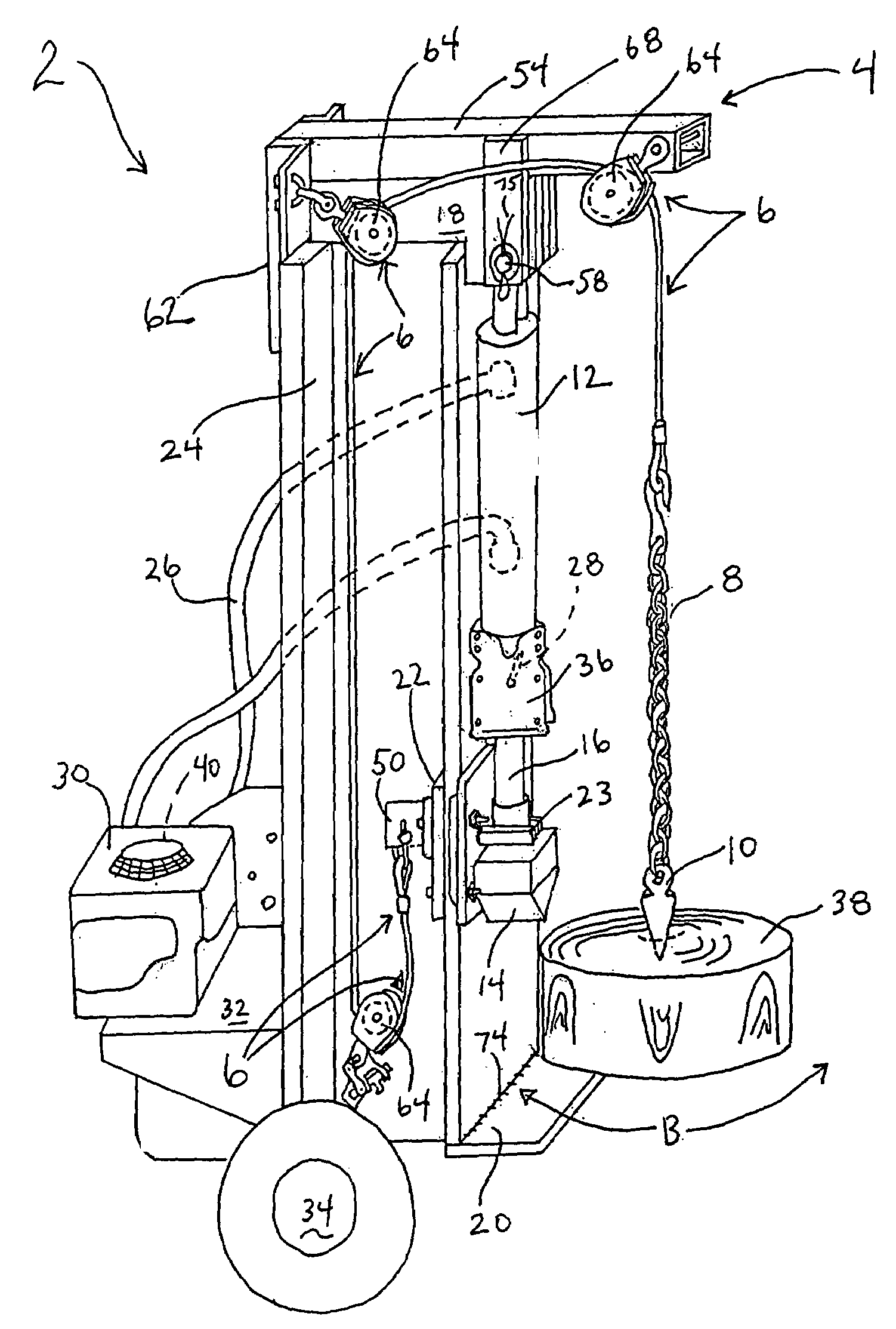
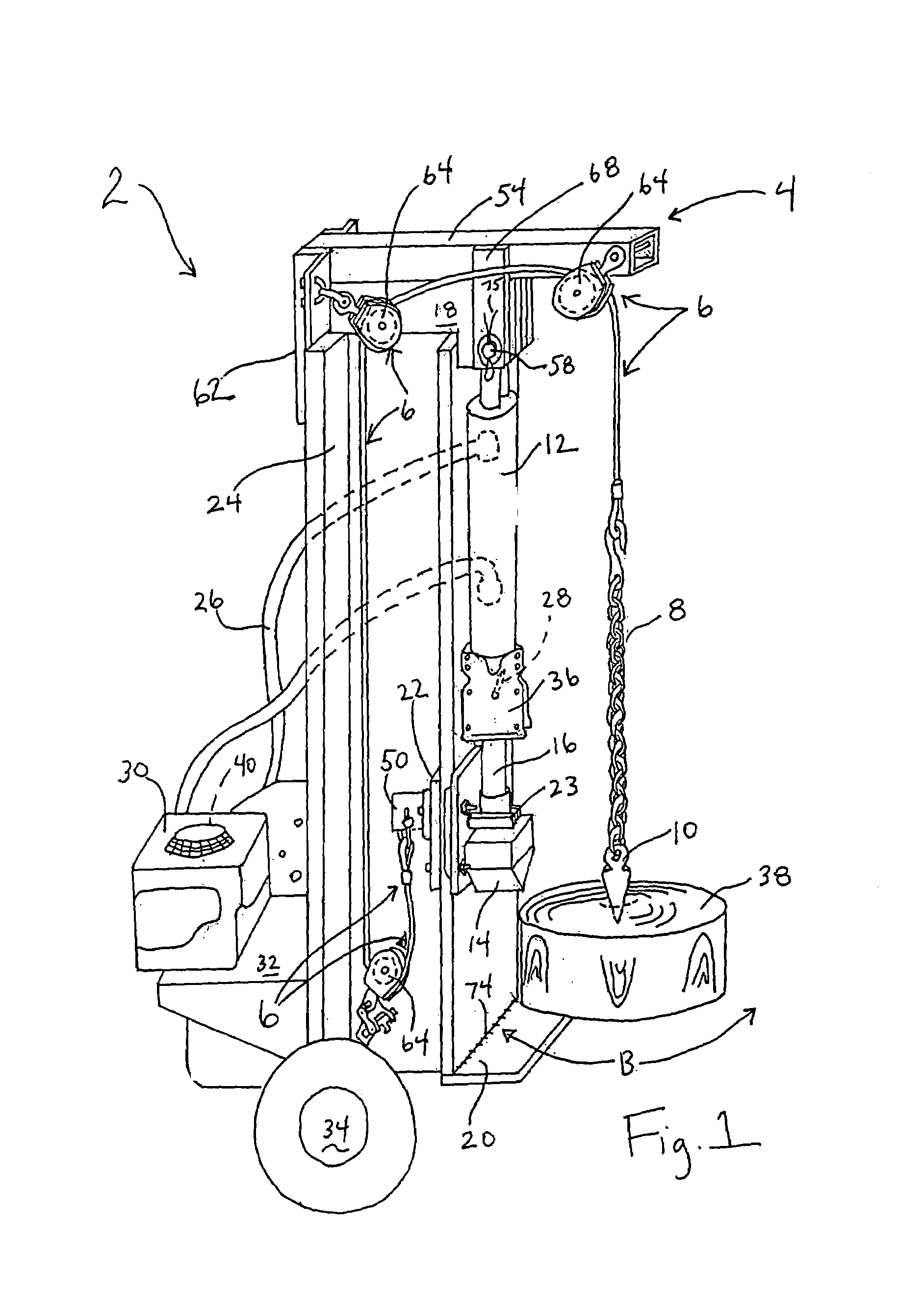
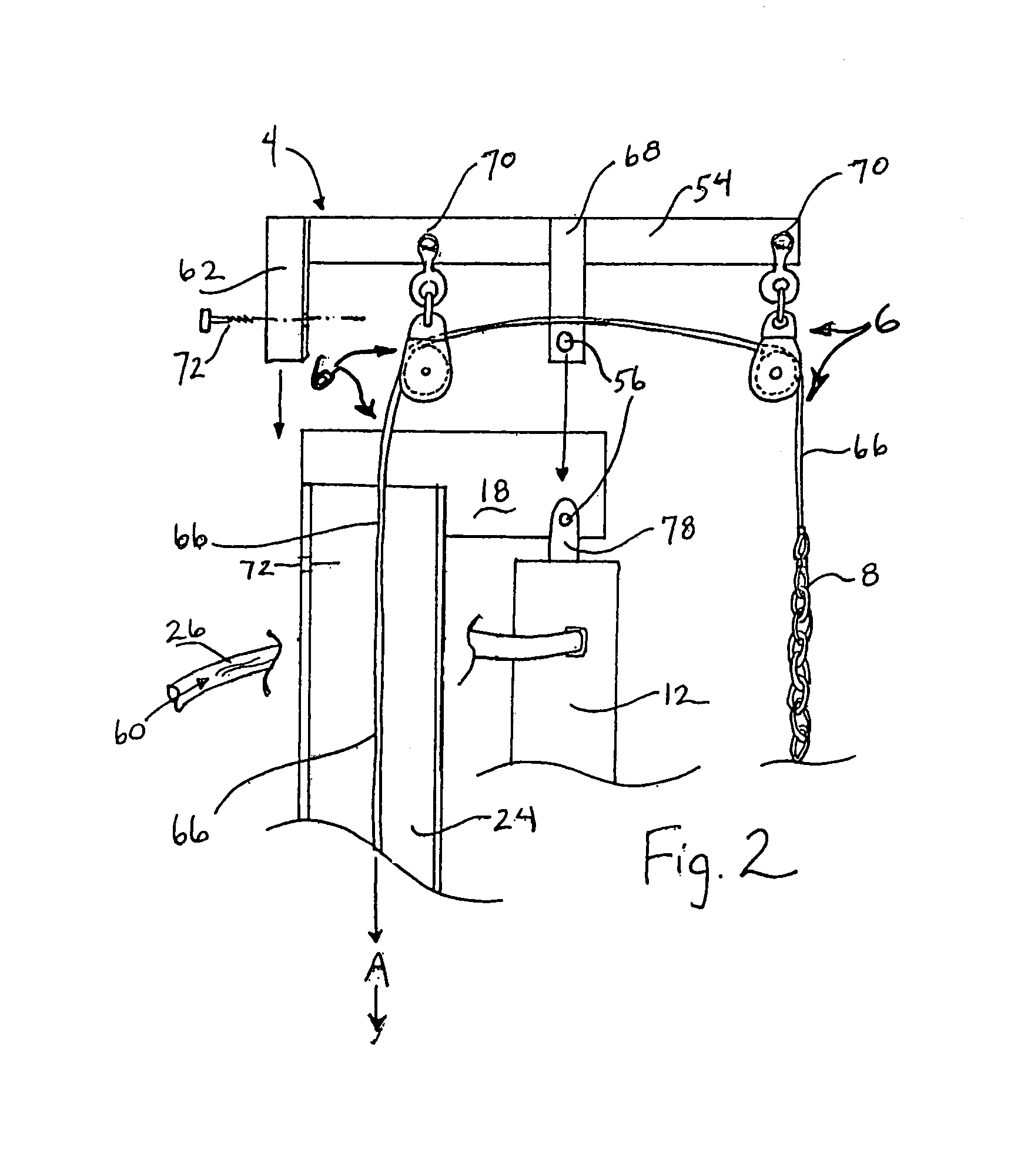
[0025]The following detailed description illustrates the invention by way of example, not by way of limitation of the scope, equivalents or principles of the invention. This description will clearly enable one skilled in the art to make and use the invention, and describes several embodiments, adaptations, variations, alternatives and uses of the invention, including what is presently believed to be the best modes of carrying out the invention.

[0026]In this regard, the invention is illustrated in the several figures, and is of sufficient complexity that the many parts, interrelationships, and sub-combinations thereof simply cannot be fully illustrated in a single patent-type drawing. For clarity and conciseness, several of the drawings show in schematic, or omit, parts that are not essential in that drawing to a description of a particular feature, aspect or principle of the invention being disclosed. Thus, the best mode embodiment of one feature may be shown in one drawing, and the...


PUM


Abstract

A new or retrofit block hoist for conventional, hydraulic-powered log splitters assists in the lifting, maneuvering, and positioning of large diameter, heavy logs that require multiple radial splits to section them for firewood, comprising a boom, pulley and cable system. A boom assembly is secured to the top end of the splitter guide beam and pulleys guide a lifting cable anchored to the wedge slide to a log section retainer means (dog or awl). The upward, hydraulically-powered movement of the cutting wedge along the I-beam lifts the log section as the wedge is raised into its upward, retracted position. Once lifted, the log is swung into position between the wedge and splitter foot plate. The wedge is then power extended (lowered), splitting the log. An optional turntable is securable to the footplate. The inventive block hoist can be provided as a kit.

Description

CROSS REFERENCE TO RELATED APPLICATION[0001]This is the Regular U.S. Patent Application of prior Provisional Application Ser. No. 60 / 531,701 filed Dec. 22, 2003 by the same inventor under the same title, priority of which is hereby claimed under 35 U.S. Code Section 119, 120ff, and the disclosure of which is hereby incorporated by reference.FIELD[0002]The invention relates to log splitting systems, and more particularly to block hoists for conventional hydraulic ram-powered log splitters for ease and effectiveness of lifting and positioning of logs for splitting. The inventive block hoist is of particular use in splitting large, heavy logs of a large diameter, and it may be used with new splitters or retrofitted on splitters already in use.BACKGROUND[0003]There are a variety of hydraulic ram log splitting systems for commercial and non-commercial use that have been developed in the past few decades. Initially, splitters used an engine driven pump that produced less than 1000 psi. Cu...

Claims


Application Information

Patent Timeline
Patent Type & Authority Patents(United States)
IPC IPC(8): B27L7/00B27L7/08
CPCB27L7/08B27L7/00
Inventor PETERSON, BYRON
Owner PETERSON BYRON
Why Eureka
Try Eureka