Illumination device for simulating neon lighting through use of fluorescent dyes

a technology of illumination device and fluorescent dye, which is applied in the direction of lighting support device, lighting and heating apparatus, instruments, etc., can solve the problems of inconvenient initial handling, installation and/or replacement, and the cost of neon lighting is high, and achieves the effect of increasing the cost or complexity of the illumination devi

Inactive Publication Date: 2006-03-14
LUMINII PURCHASER LLC
View PDF30 Cites 87 Cited by
  • Summary
  • Abstract
  • Description
  • Claims
  • Application Information

AI Technical Summary

Benefits of technology

[0010]The present invention is an illumination device for simulating neon lighting through use of fluorescent dyes, thus allowing for emission of light in colors that cannot ordinarily be achieved by use of LEDs alone without significant increase in cost or complexity of the illumination device.

Problems solved by technology

Because of the fragility and heavy weight, primarily due to its supporting infrastructure, neon lighting is expensive to package and ship.
Moreover, it is extremely awkward to initially handle, install, and / or replace.
However, the twin attributes of neon lighting, uniformity and brightness, have proven to be difficult obstacles to overcome as such attempts to simulate neon lighting have largely been stymied by the tradeoffs between light distribution to promote the uniformity and brightness.
While it is important that the disadvantages of neon lighting be avoided (for example, weight and fragility), an illumination device would have little commercial or practical value if the proper light uniformity and intensity could not be obtained.
Nevertheless, a problem with illumination devices using leaky waveguides and LEDs, as described and claimed in U.S. patent application Ser. No. 09 / 982,705, is that the available visible color spectrum is limited by the finite availability of LED colors.

Method used


Image

  • Illumination device for simulating neon lighting through use of fluorescent dyes
  • Illumination device for simulating neon lighting through use of fluorescent dyes
  • Illumination device for simulating neon lighting through use of fluorescent dyes

Examples


example 1

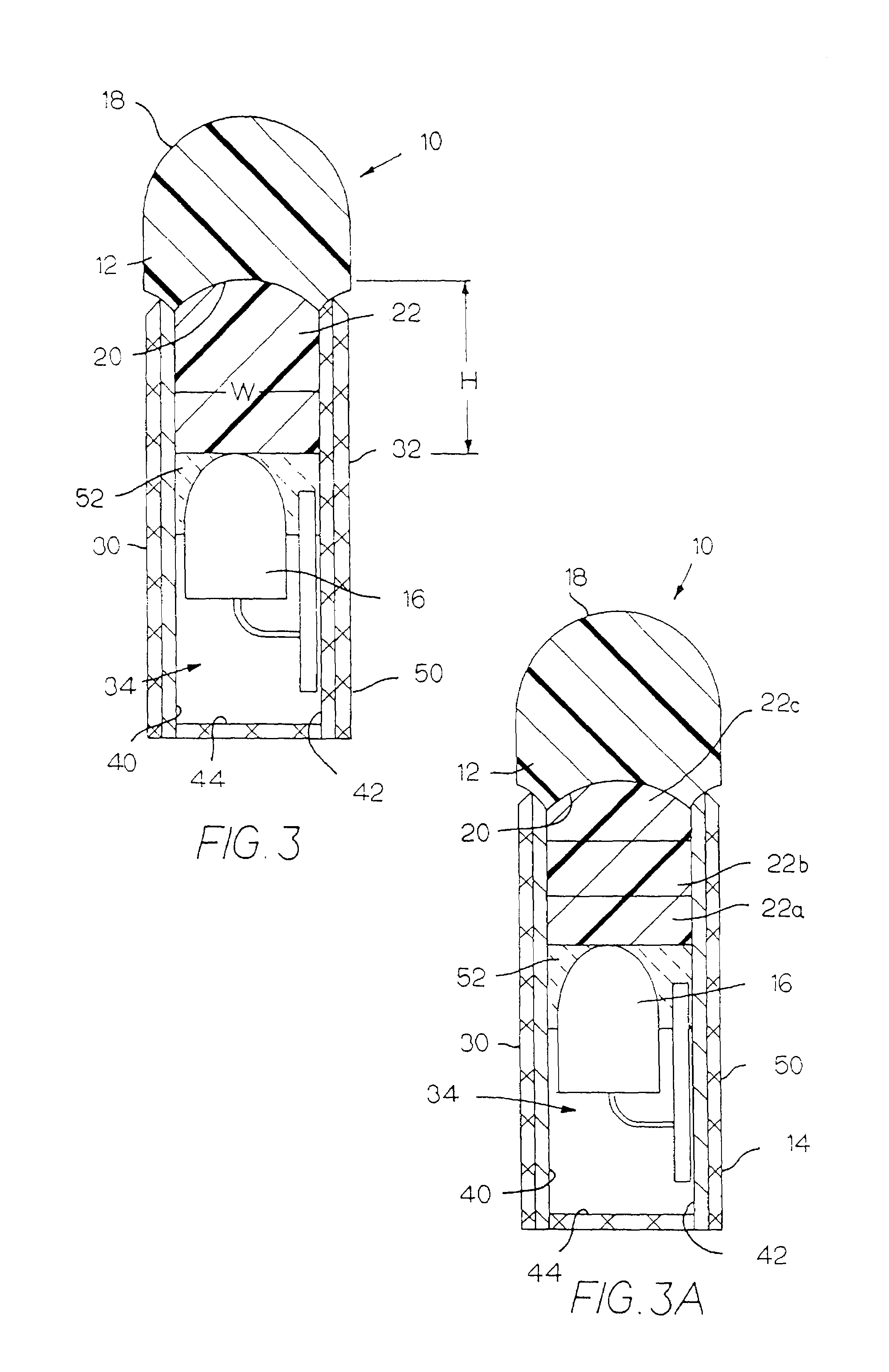
[0038]In this first example, an illumination device 10 is constructed with a length L of approximately 4.75 inches and has a cross-section as shown in FIG. 3. The light source 16 is a string of nine contiguously mounted, high-intensity LEDs spaced at approximately 0.50-inch intervals. Furthermore and more importantly, the LEDs in the example are blue, emitting light with a wavelength of approximately 470 nm and having color coordinates of x≅0.111 and y≅0.058 on the CIE Chromaticity Diagram.

[0039]The LEDs are operated at approximately 20 mA. In order to simplify the manufacturing and assembly process, it is preferred that the LEDs be operated at a substantially constant current and power. However, by varying the current, the resultant perceived color may be affected.

[0040]Finally, referring again to FIG. 3, the intermediate light-transmitting medium 22 in this example has a height H of approximately 0.625 inches, a width W of approximately 0.375 inches, and a length essentially ident...

example 2

[0045]In this example, an illumination device 10 is constructed with a length L of approximately 4.625 inches and also has a cross-section similar to that shown in FIG. 3. The light source 16 is a string of nine contiguously mounted, high-intensity LEDs spaced at approximately 0.50-inch intervals and operated at approximately 20 mA. Furthermore, the LEDs in the example are again blue, emitting light with a wavelength of approximately 470 nm and having color coordinates of x≅0.111 and y≅0.058 on the CIE Chromaticity Diagram.

[0046]Referring again to FIG. 3, the intermediate light-transmitting medium 22 in this example has a height H of approximately 0.375 inches, a width W of approximately 0.1875 inches, and a length essentially identical to that of the illumination device, 4.625 inches. The intermediate light-transmitting medium 22 is composed of a substantially translucent polyurethane tinted with a combination of fluorescent dyes in the following proportions:

[0047]

TABLE 2Mass (g)Po...

example 3

[0049]In this example, an illumination device 10 is constructed with a length L of approximately 3.00 inches and also has a cross-section similar to that shown in FIG. 3. The light source 16 is a string of six contiguously mounted, high-intensity LEDs spaced at approximately 0.50-inch intervals and operated at approximately 20 mA. Furthermore, the LEDs in the example are again blue, emitting light with a wavelength of approximately 470 nm and having color coordinates of x≅0.111 and y≅0.058 on the CIE Chromaticity Diagram.

[0050]Referring again to FIG. 3, the intermediate light-transmitting medium 22 in this example has a height H of approximately 0.400 inches, a width W of approximately 0.1875 inches, and a length essentially identical to that of the illumination device, 3.00 inches. The intermediate light-transmitting medium 22 is composed of a substantially translucent polyurethane tinted with a combination of fluorescent dyes in the following proportions:

[0051]

TABLE 3Mass (g)Polyu...


PUM


Abstract

An illumination device simulates neon lighting and allows for emission of light in colors that cannot ordinarily be achieved by use of LEDs alone through the incorporation of a light color conversion system into the illumination device. This light color conversion system comprises an intermediate light-transmitting medium tinted with a predetermined combination of one or more fluorescent dyes. Light emitted from the light source of the illumination device is directed into the intermediate light-transmitting medium and interacts with the fluorescent dyes contained therein. This light is partially absorbed by each of the fluorescent dyes of the intermediate light-transmitting medium, and a lower-energy light is then emitted from each of the fluorescent dyes and into the light-receiving surface of the waveguide. Thus, selection of appropriate combinations of dyes results in various colors being emitted from the illumination device.

Description

CROSS-REFERENCE TO RELATED APPLICATIONS[0001]The present application claims priority to U.S. Provisional Application Ser. No. 60 / 387,076 filed Jun. 6, 2002 and is a continuation-in-part of U.S. Utility application Ser. No. 09 / 982,705 filed Oct. 18, 2001 now U.S. Pat. No. 6,592,238, the entire disclosures of which are incorporated herein by reference.BACKGROUND OF THE INVENTION[0002]The present invention relates to an illumination device for simulating neon lighting using high-intensity, low-voltage light sources, an illumination device ideally adapted for lighting, signage and advertising uses.[0003]Neon lighting, which is produced by the electrical stimulation of the electrons in the low-pressure neon gas-filled glass tube, has been a main stay in advertising and for outlining channel letters and building structures for many years. A characteristic of neon lighting is that the tubing encompassing the gas has an even glow over its entire length irrespective of the viewing angle. Thi...

Claims


Application Information

Patent Timeline
Patent Type & Authority Patents(United States)
IPC IPC(8): F21V21/00F21S4/00F21V5/00F21V8/00F21V9/16F21V23/04F21V31/04
CPCG02B6/001F21S4/007F21V5/00G02B6/0005F21V23/0407F21V2200/30F21Y2101/02F21Y2103/003F21V31/04F21S4/26F21Y2103/10F21Y2115/10
Inventor HULSE, GEORGE R.DOMINICK, JOHN R.CLEAVER, MARK J.ERIKSSON, ERIC OLAV
Owner LUMINII PURCHASER LLC
Why Eureka
Try Eureka