Thermal shield turbine airfoil

a technology of thermal shield turbine and airfoil, which is applied in the direction of machines/engines, climate sustainability, sustainable transportation, etc., can solve the problems of increasing casting cost, reducing the effective yield of casting process, and relatively brittle ceramic cores

Inactive Publication Date: 2006-03-14
GENERAL ELECTRIC CO
View PDF12 Cites 62 Cited by
  • Summary
  • Abstract
  • Description
  • Claims
  • Application Information

AI Technical Summary

Problems solved by technology

The ceramic cores are relatively brittle and subject to damage during the casting process.
If the cores are too thin or weak and prone to breakage, the effective yield of the casting process is reduced which correspondingly increases casting cost.

Method used


Image

  • Thermal shield turbine airfoil
  • Thermal shield turbine airfoil
  • Thermal shield turbine airfoil

Examples


Embodiment Construction

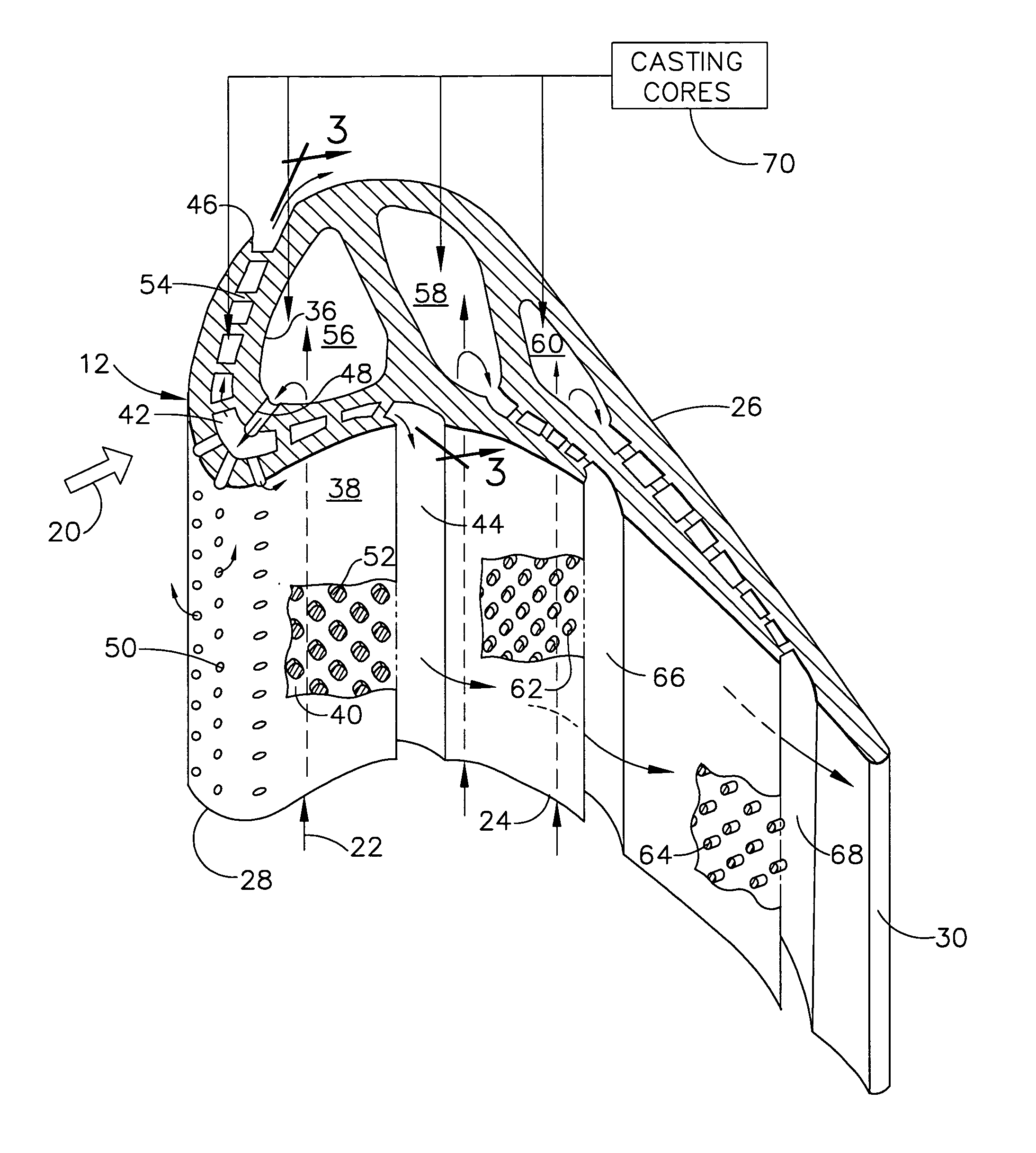
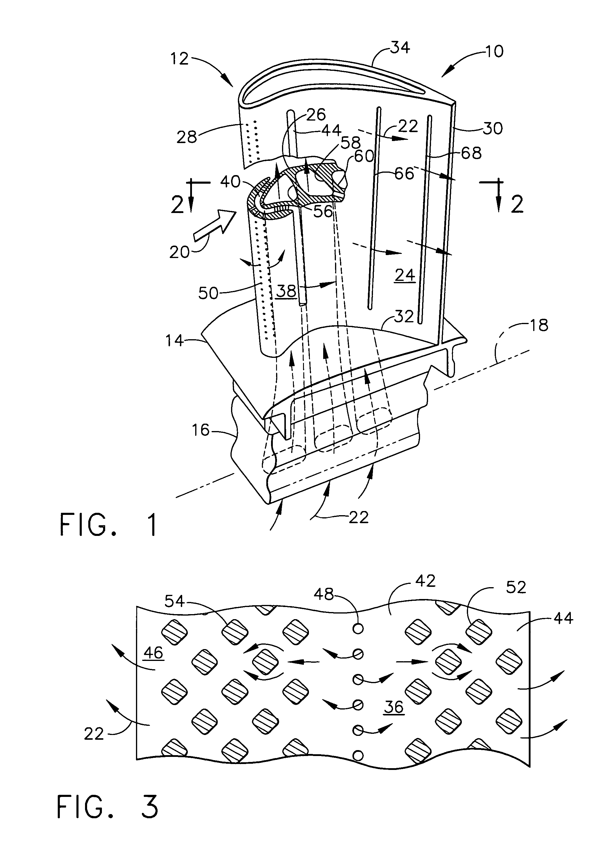
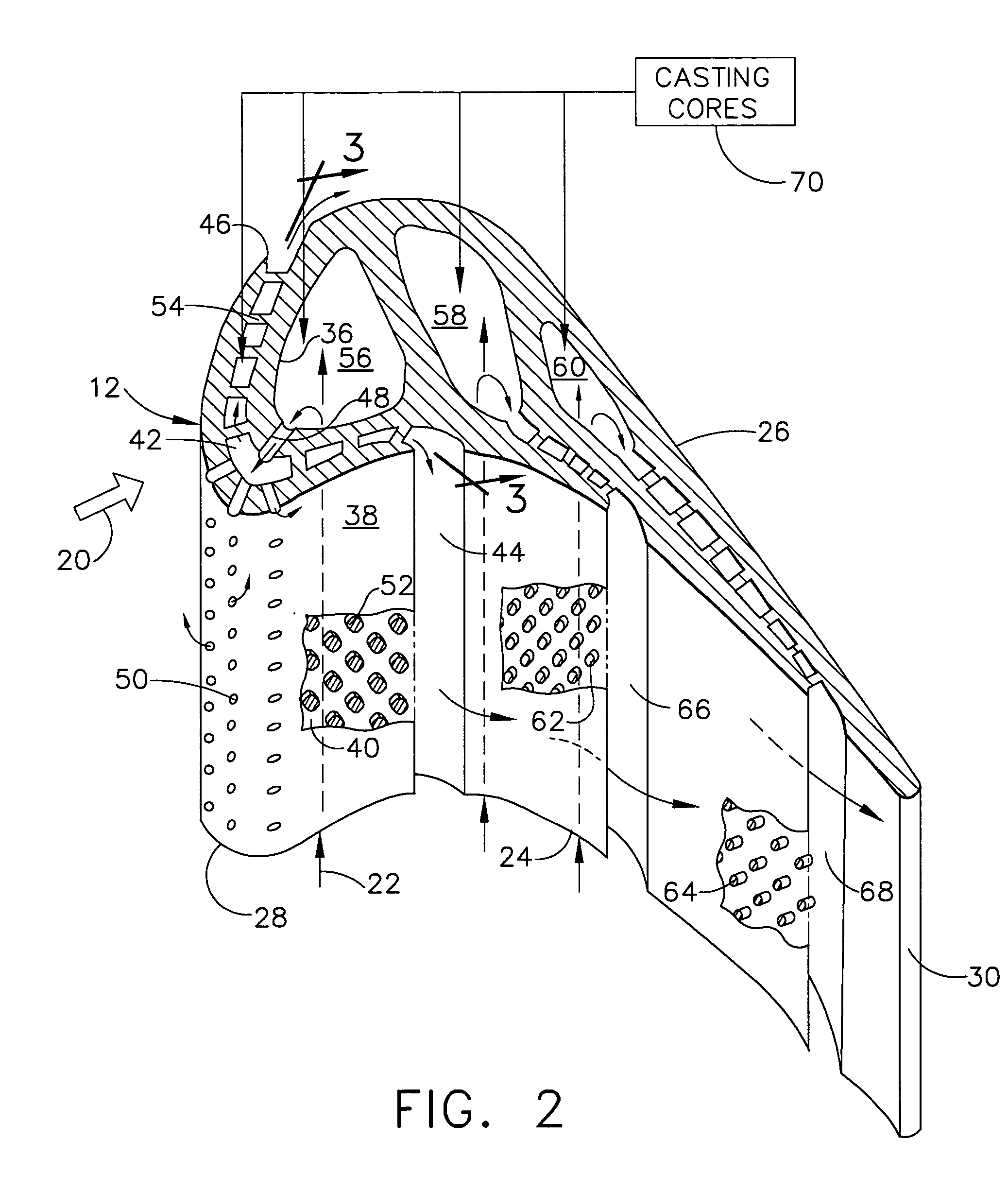
[0023]Illustrated in FIG. 1 is an exemplary turbine rotor blade 10 for a gas turbine engine, such as a turbofan aircraft engine. The blade includes an airfoil 12 of suitable shape integrally formed with a platform 14 and supporting dovetail 16 in a unitary configuration.

[0024]The dovetail 16 is conventional and includes axial tangs or lobes which are trapped in a complementary axial dovetail groove in the perimeter of a supporting rotor disk (not shown) in the turbine engine. The axial centerline axis 18 of the turbine engine is illustrated for point of reference, with the exemplary dovetail being configured for axial entry into the corresponding dovetail slot. A full row of the blades 10 are mounted around the perimeter of the disk in the engine.

[0025]During operation, hot combustion gases 20 are generated in the combustor (not shown) of the engine and suitably channeled to the row of turbine rotor blades through a conventional turbine nozzle (not shown) having a row of stator vane...


PUM


Abstract

A turbine airfoil includes opposite pressure and suction sides joined together at leading and trailing edges. An outwardly convex nose bridge bridges the pressure and suction sides behind the leading edge, and is integrally joined to a complementary thermally insulating shield spaced therefrom to define a bridge channel. The shield includes the leading edge and wraps laterally aft around the nose bridge along both the pressure and suction sides.

Description

[0001]The U.S. Government may have certain rights in this invention pursuant to contract number F33615-02-C-2212 awarded by the U.S. Department of the Air Force.BACKGROUND OF THE INVENTION[0002]The present invention relates generally to gas turbine engines, and, more specifically, to turbines therein.[0003]In a gas turbine engine air is pressurized in a compressor and mixed with fuel in a combustor for generating hot combustion gases. Energy is extracted from the gases in a high pressure turbine which powers the compressor, and additional energy is extracted in a low pressure turbine which typically powers an upstream fan in a typical turbofan aircraft engine application.[0004]Engine efficiency and performance can be increased by increasing temperature of the combustion gases, but the hot combustion gases affect the life of turbine components heated thereby. Typical components such as nozzle vanes and rotor blades in the turbines are bathed with the hot combustion gases during opera...

Claims


Application Information

Patent Timeline
Patent Type & Authority Patents(United States)
IPC IPC(8): F01D5/18
CPCF01D5/187Y02T50/676Y02T50/60
Inventor LEE, CHING-PANGBUNKER, RONALD SCOTT
Owner GENERAL ELECTRIC CO
Why Eureka
Try Eureka