Energy calculation methods in power distribution systems

Active Publication Date: 2006-03-14
ABB (SCHWEIZ) AG
View PDF4 Cites 29 Cited by
  • Summary
  • Abstract
  • Description
  • Claims
  • Application Information

AI Technical Summary

Benefits of technology

[0007]Accordingly, there is a continuing need for power distribution systems having metho

Problems solved by technology

In order to provide this integrated protection and monitoring, prior distribution systems have required costly and difficult to implement solutions.
The control decisions by the separate system performing feed management decisions is made more

Method used


Image

  • Energy calculation methods in power distribution systems
  • Energy calculation methods in power distribution systems
  • Energy calculation methods in power distribution systems

Examples


Embodiment Construction

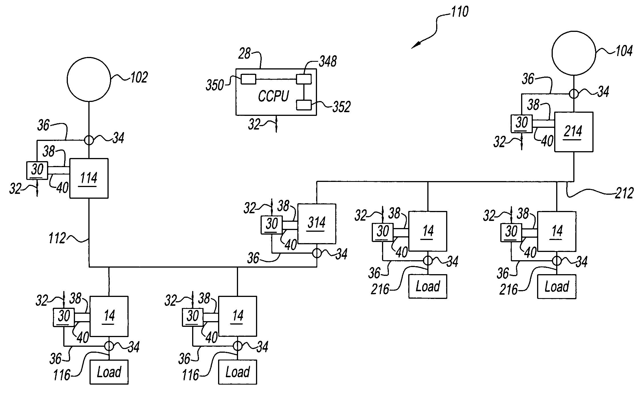
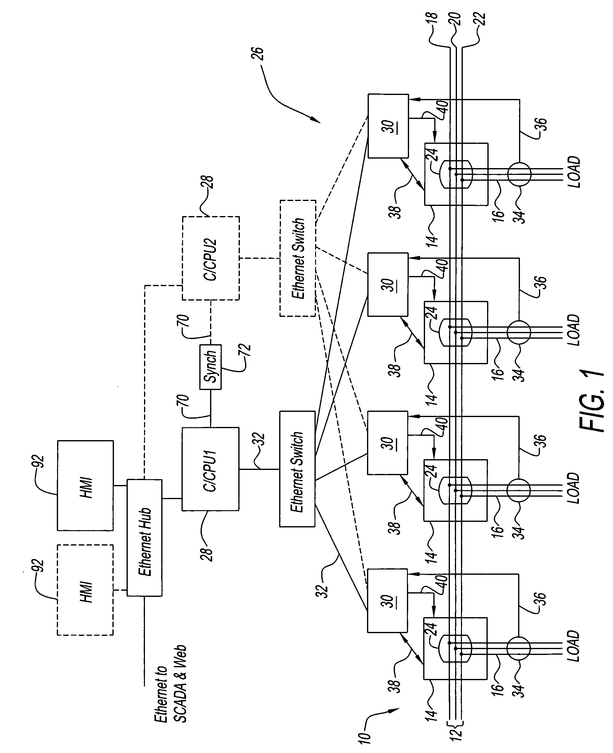
[0016]Referring now to the drawings and in particular to FIG. 1, an exemplary embodiment of a power distribution system generally referred to by reference numeral 10 is illustrated. Power distribution system 10 distributes power from at least one power bus 12 through a number or plurality of circuit breakers 14 to branch circuits 16.

[0017]Power bus 12 is illustrated, by way of example, as a three-phase power system having a first phase 18, a second phase 20, and a third phase 22. Power bus 12 can also include a neutral phase (not shown). Power distribution system 10 is illustrated, for purposes of clarity, as distributing power from power bus 12 to four circuits 16 by four breakers 14. Of course, it is contemplated by the present disclosure for power bus 12 to have any desired number of phases and / or for system 10 to have any desired number of circuit breakers 14.

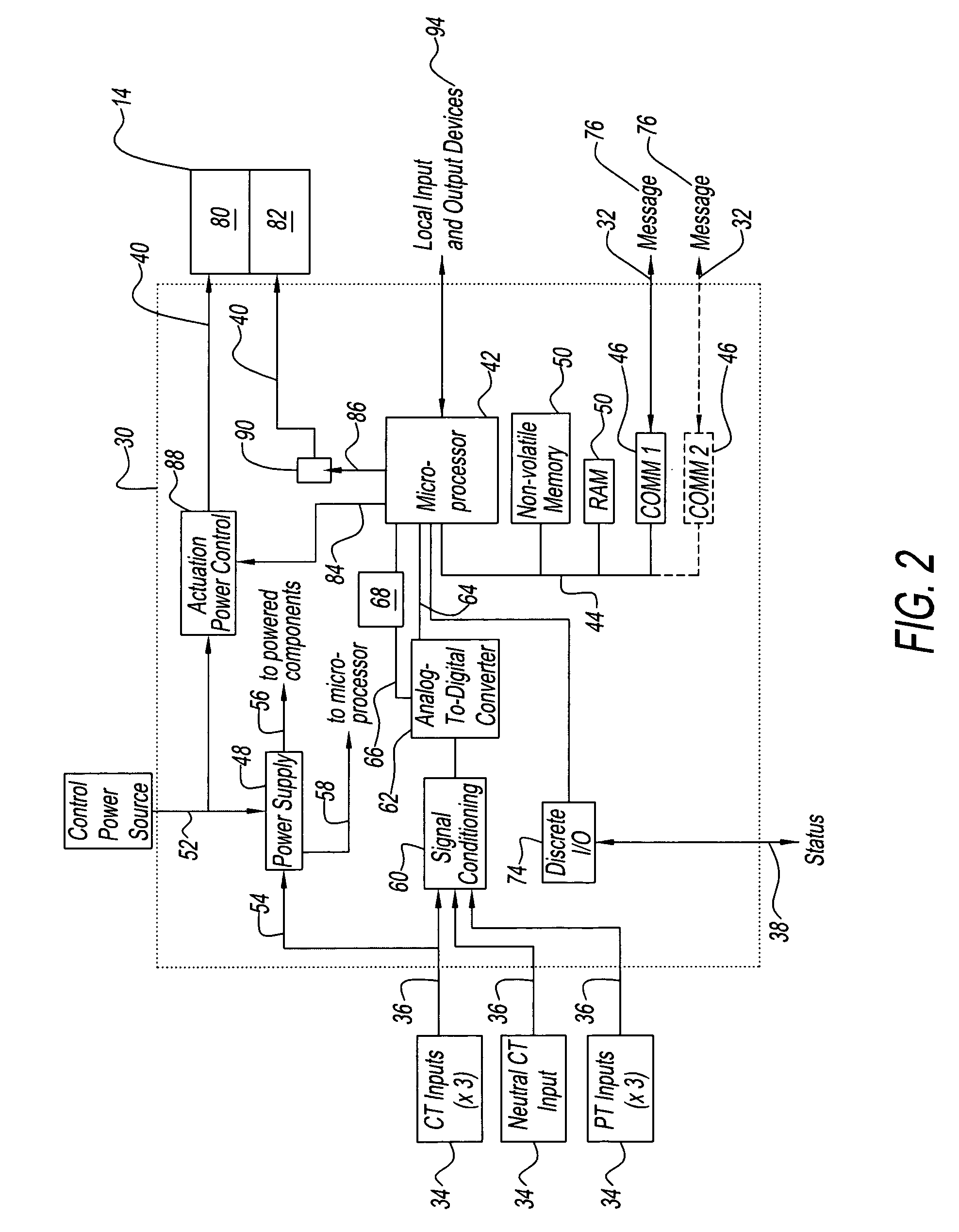
[0018]Each circuit breaker 14 has a set of separable contacts 24 (illustrated schematically). Contacts 24 selectively pla...


PUM


Abstract

A method of performing energy calculations in a power distribution system is provided. The method includes sampling a first voltage at a first module in the power distribution system; communicating the first voltage from the first module to a central controller; performing an energy calculation in the central controller based at least in part on the first voltage; and applying the energy calculation to a second module in the power distribution system. In some embodiments, the energy calculation is also based upon a second current from the second module.

Description

CROSS REFERENCE TO RELATED APPLICATIONS[0001]This application claims benefit of U.S. Provisional Application Ser. No. 60 / 438,159 filed on Jan. 6, 2003, the content of which is incorporated by reference herein.BACKGROUND OF INVENTION[0002]The present disclosure relates to power distribution systems. More particularly, the present disclosure relates to energy calculation methods in power distribution systems.[0003]Industrial power distribution systems commonly divide incoming power into a number of branch circuits. The branch circuits supply power to various equipment (i.e., loads) in the industrial facility. Circuit breakers are typically provided in each branch circuit to facilitate protecting equipment within the branch circuit. Circuit breakers are designed to open and close a circuit by non-automatic means and to open the circuit automatically on a predetermined over-current without damage to itself when properly applied within its rating. The circuit breakers commonly include pr...

Claims


Application Information

Patent Timeline
IPC IPC(8): G01R7/00G06F1/12H02H1/00H02H3/00H02H3/05H02J13/00H04L12/24
CPCG06F1/12H02J13/0055H02J13/0062H02J13/0079H02J13/0086Y04S20/224H02H3/006H02H3/05H02J3/005H02J13/0072H02J2003/001H02J2003/146Y02B70/3216Y04S20/221H02H1/0061H02J2310/64H02J13/00012H02J13/00018H02J13/00016H02J13/0004Y02B70/30Y04S20/222Y04S50/10Y02B70/3225H02J3/007H02J3/0012H02J3/00125
Inventor LAVOIE, GREGORY P.PAPALLO, THOMAS F.BERKCAN, ERTUGRULPREMERLANI, WILLIAM JAMES
Owner ABB (SCHWEIZ) AG
Why Eureka
Try Eureka