Clock shift circuit for gradual frequency change

a technology of clock shift and frequency change, applied in the field of clock shift circuits, can solve the problems of circuitry that uses the clock and generates sudden changes in circuitry that uses the clock and generate abnormal voltages, etc., to prevent the consumption of electric current, reduce and increase the number of clock pulses per unit time.

Active Publication Date: 2006-03-14
MONTEREY RES LLC
View PDF10 Cites 27 Cited by
  • Summary
  • Abstract
  • Description
  • Claims
  • Application Information

AI Technical Summary

Benefits of technology

[0018]In the invention as described above, the control signal controls the clock generating circuit (the selector circuit and the decimated clock generating circuit) according to a mode change signal, thereby gradually changing the clock signal at the time of a change of operation modes. Namely, when a change is made from a clock active state using a normal operating frequency to a clock suspended state, the clock signal is controlled such that the number of clock pulses per unit time is decreased gradually. When a change is made from a clock suspended state to a clock active state using a normal operating frequency, the clock signal is controlled such that the number of clock pulses per unit time is increased gradually. This avoids a sudden clock change, thereby preventing the consumption of electric currents from changing suddenly in circuitry using the clock signal, which prevents a regulator from generating an abnormal voltage.
[0019]Moreover, the use of the frequency divider and the decimated clock generating circuit makes it possible to generate a clock signal having any desired frequency of n / m (n, m: integers) that cannot be generated by use of the frequency divider alone. This achieves finer changes when the clock frequency is changed. Moreover, hardware-based control according to the invention can achieve high-speed operation that is not attainable by software-based control according to the conventional art.

Problems solved by technology

With the widespread use of portable equipment and an increase in circuit size, standby power consumed by load capacitance associated with clock signal lines can no longer be disregarded, making it necessary to control the start / stop of clock signals.
When a clock is suddenly changed in such a manner, circuitry that uses the clock generates a sudden change in the consumption of electric currents.
This may cause regulators inside semiconductor integrated circuits to generate abnormal voltages.

Method used


Image

  • Clock shift circuit for gradual frequency change
  • Clock shift circuit for gradual frequency change
  • Clock shift circuit for gradual frequency change

Examples


Embodiment Construction

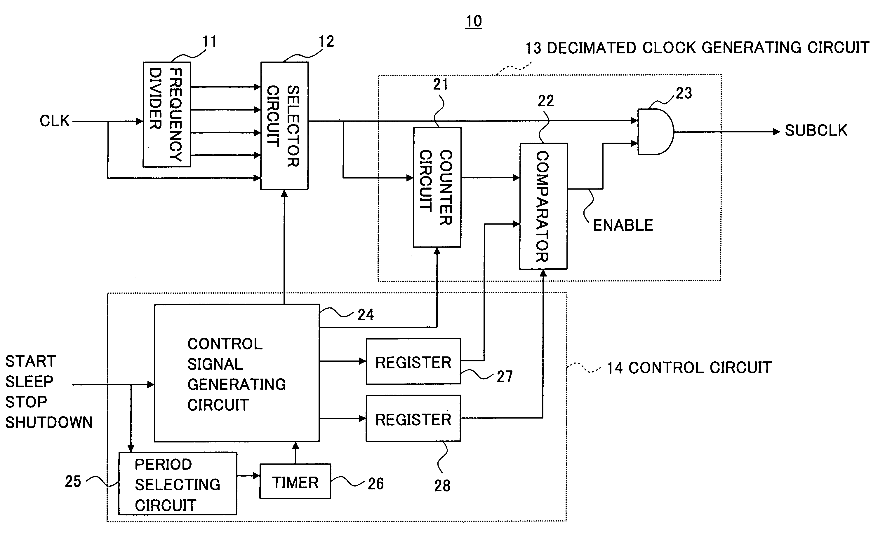
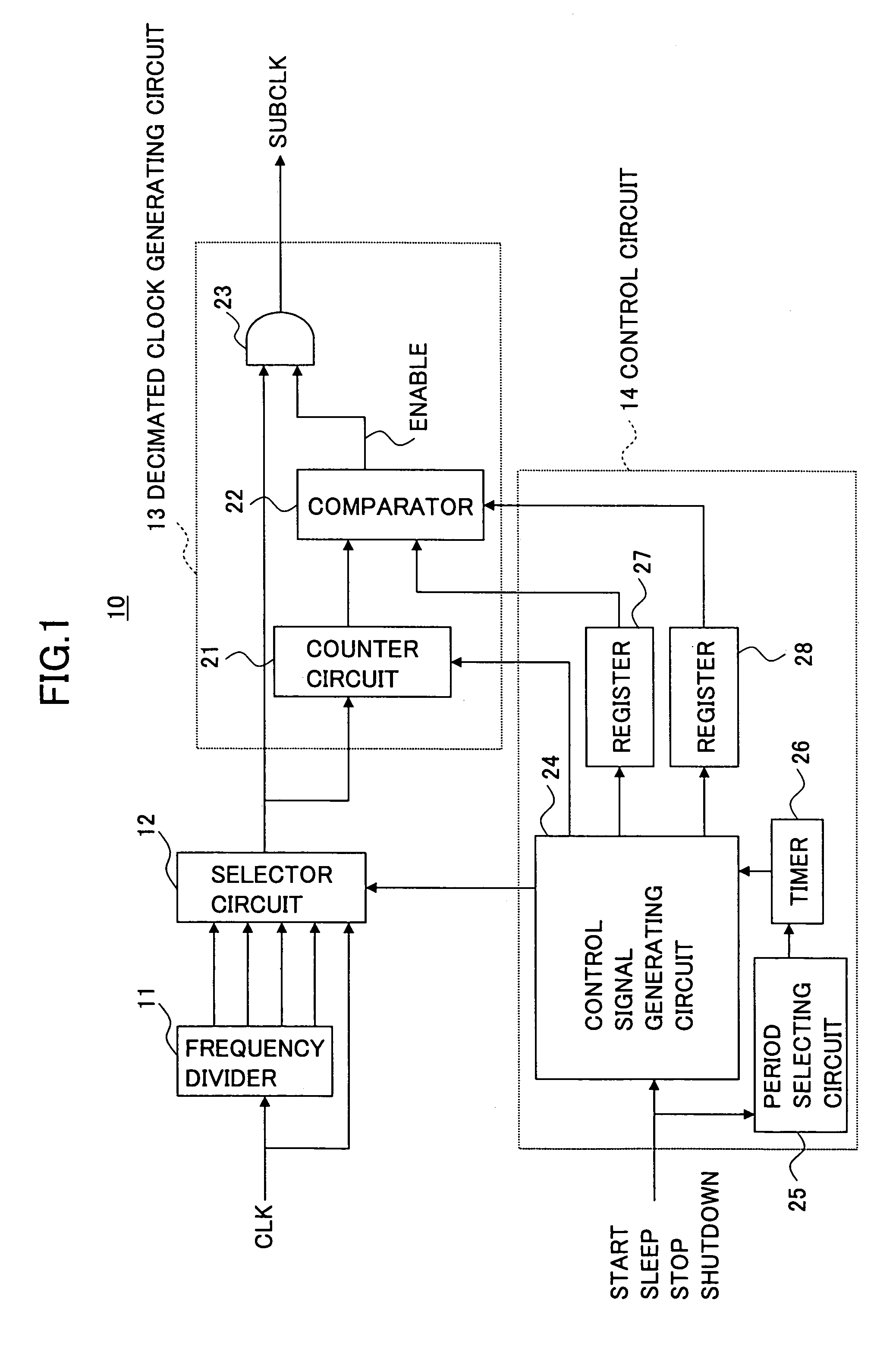
[0027]The technology disclosed in these patent documents only teaches a clock generating circuit with the function to switch clock frequencies. There is no mention of a construction by which a clock is gradually speeded up or gradually speeded down in response to the switching of operation modes. There is a related-art technology that controls the speeding-up operation of a clock by use of software. This technology has a drawback in that high speed operation cannot be attained, and also has shortcomings in that a clock having a frequency between 1 / n and 1 / (n+1) cannot be generated.

[0028]Accordingly, there is a need for a clock shift circuit that can change a clock frequency gradually in response to a change of operation modes.

[0029]It is a general object of the present invention to provide a clock shift circuit that substantially obviates one or more problems caused by the limitations and disadvantages of the related art.

[0030]In the following, embodiments of the present invention w...


PUM


Abstract

A circuit for changing clocks includes a clock generating circuit which generates an output clock signal by controlling a frequency of an original clock signal, and a control circuit which controls the clock generating circuit in response to an operation mode change signal indicative of a change from a first operation mode to a second operation mode of an external circuit operating based on the output clock signal, thereby changing the output clock signal from a first frequency corresponding to the first operation mode to an intervening frequency and then from the intervening frequency to a second frequency corresponding to the second operation mode, the intervening frequency having a frequency between the first frequency and the third frequency.

Description

CROSS-REFERENCE TO RELATED APPLICATIONS[0001]The present application is based upon and claims the benefit of priority from the prior Japanese Patent Application No. 2003-355061 filed on Oct. 15, 2003, with the Japanese Patent Office, the entire contents of which are incorporated herein by reference.BACKGROUND OF THE INVENTION[0002]1. Field of the Invention[0003]The present invention generally relates to circuits for generating a clock signal of a desired frequency, and particularly relates to a clock shift circuit which changes a clock signal from a given frequency to another frequency.[0004]2. Description of the Related Art[0005]In large-scale logic circuits such as semiconductor integrated circuits, a technology for controlling the supply of clock signals inside a circuit as circumstances demand is becoming increasingly important for the purpose of cutting down power consumption. Especially in portable equipment for which power consumption is an important issue, such technology is...

Claims


Application Information

Patent Timeline
Patent Type & Authority Patents(United States)
IPC IPC(8): H03B19/00G06F1/08H03K5/00H03K5/159
CPCG06F1/08
Inventor MATSUI, SATOSHIOZAWA, YUKIHIROSUETAKE, SEIJI
Owner MONTEREY RES LLC
Why Eureka
Try Eureka