Reflection barrier for panoramic display

a technology of reflection barrier and panoramic display, which is applied in the field of panoramic visual display system, can solve the problems of increasing difficulty, inability to completely hide the seams between images, and ineffective current methods for blending the edges of images from adjacent projectors, etc., and achieves no seams and good color matching

Active Publication Date: 2006-03-14
EVANS & SUTHERLAND COMP
View PDF21 Cites 32 Cited by
  • Summary
  • Abstract
  • Description
  • Claims
  • Application Information

AI Technical Summary

Benefits of technology

[0014]It has been recognized that it would be advantageous to develop a direct view display system that can project a wide field of view from a single projection location that is more nearly optimized for a uniform display, and provides good color matching and no seams.
[0015]It has also been recognized that it would be advantageous to develop a system and method for reducing light scattering with a panoramic display system.

Problems solved by technology

However, it becomes increasingly difficult with increasing field of view to place projectors in locations that provide uniform illumination and resolution, yet are still hidden from view.
In addition, current methods for blending the edges of images from adjacent projectors are not completely effective at hiding the seams between images, and color matching of adjacent images from multiple projectors is very difficult.
The common result is composite images with noticeable seams and inconsistent coloring from one portion of the image to another.
The geometry shown in FIGS. 14 and 15 creates problems for projectors in general and for panoramic displays with multiple projectors in particular.
However, it is impossible to locate multiple projectors at a single point in space.
Additionally, the low f-number lenses required for CRT projectors normally used do not have sufficient depth of focus to allow positioning at the preferred location 130.
Also, large projectors in these positions are problematic for training applications that use motion bases.
The large mass of multiple projectors placed high above the screen creates an unacceptably large moment of inertia for simulators or other applications incorporating motion systems.
The type of scanner that has been used with laser projectors in the past is not capable of the wide angle, tilted scan required for both a wide angle virtual display and a panoramic real image display.
Since such systems require dynamic synchronization of two elements rotating at different rates while maintaining precise optical alignment through multiple reflections, they are expensive to produce, suffer from accuracy problems, and are heavy and difficult to balance.
Consequently, they are seldom used for high speed scanning systems.
This type of projector is limited in image size vs. projection distance, and therefore creates a narrow image.
This method is unsuitable for a panoramic display because it magnifies the pixels in both the horizontal and vertical directions.
Additionally, bandwidth limitations have hindered the development of a high resolution panoramic display from a single projector modulating a single laser beam.
Unfortunately, mere use of a GLV does not address the problem of creating a panoramic display on a curved screen.
One problem frequently encountered with panoramic display systems, whether real or virtual, is light scattering.
This scattered light tends to wash out the image, and reduce the contrast of the display.
Obviously, this adversely affects the quality of the image.

Method used


Image

  • Reflection barrier for panoramic display
  • Reflection barrier for panoramic display
  • Reflection barrier for panoramic display

Examples


Embodiment Construction

[0042]Reference will now be made to the exemplary embodiments illustrated in the drawings, and specific language will be used herein to describe the same. It will nevertheless be understood that no limitation of the scope of the invention is thereby intended. Alterations and further modifications of the inventive features illustrated herein, and additional applications of the principles of the inventions as illustrated herein, which would occur to one skilled in the relevant art and having possession of this disclosure, are to be considered within the scope of the invention.

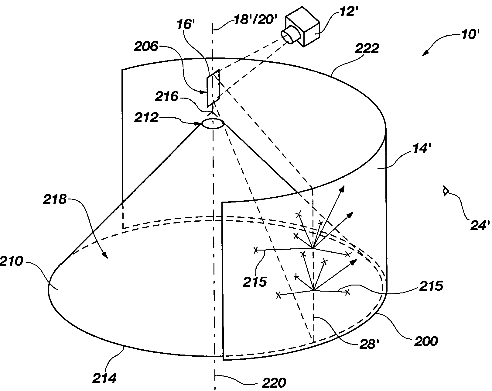
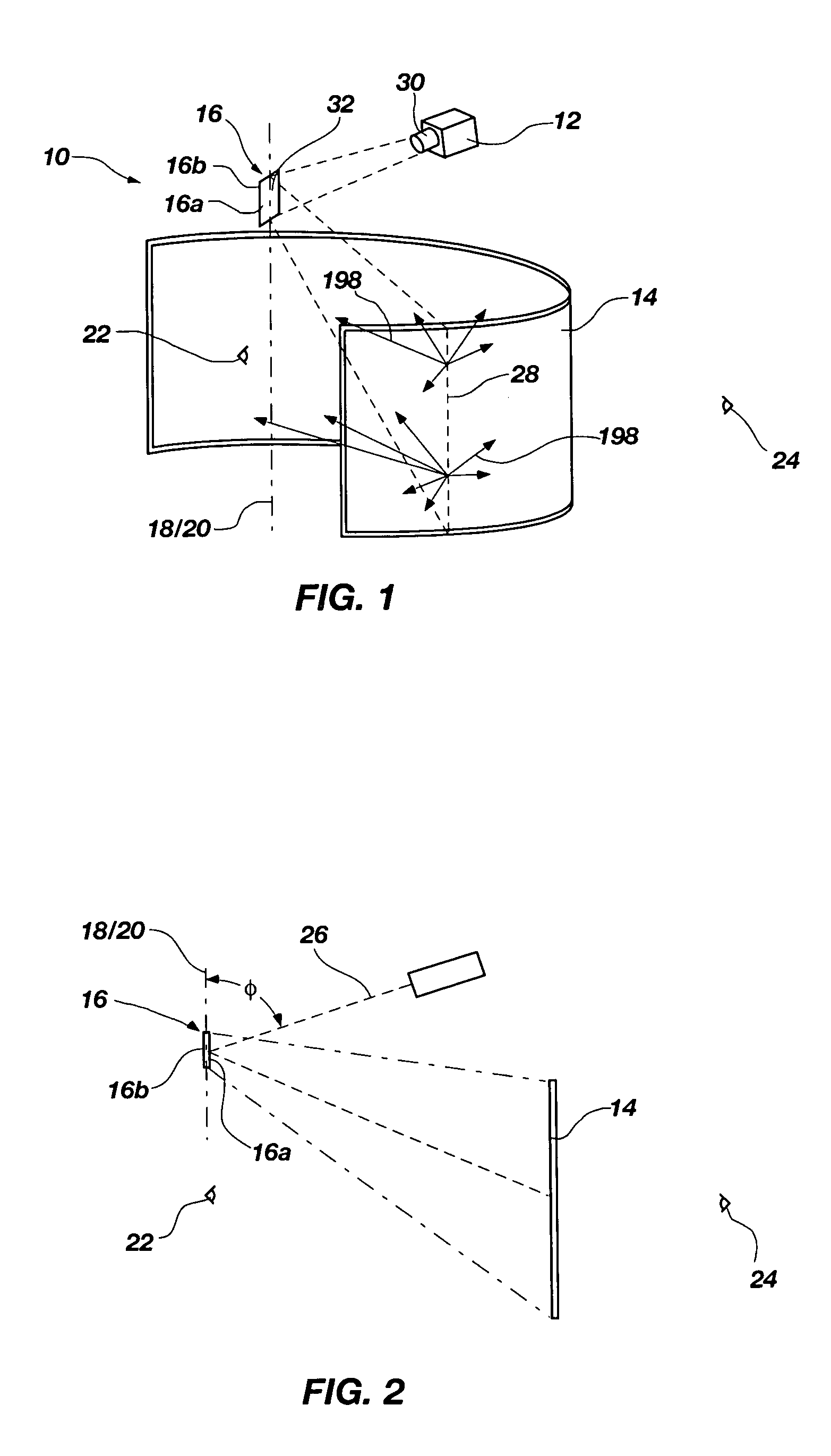
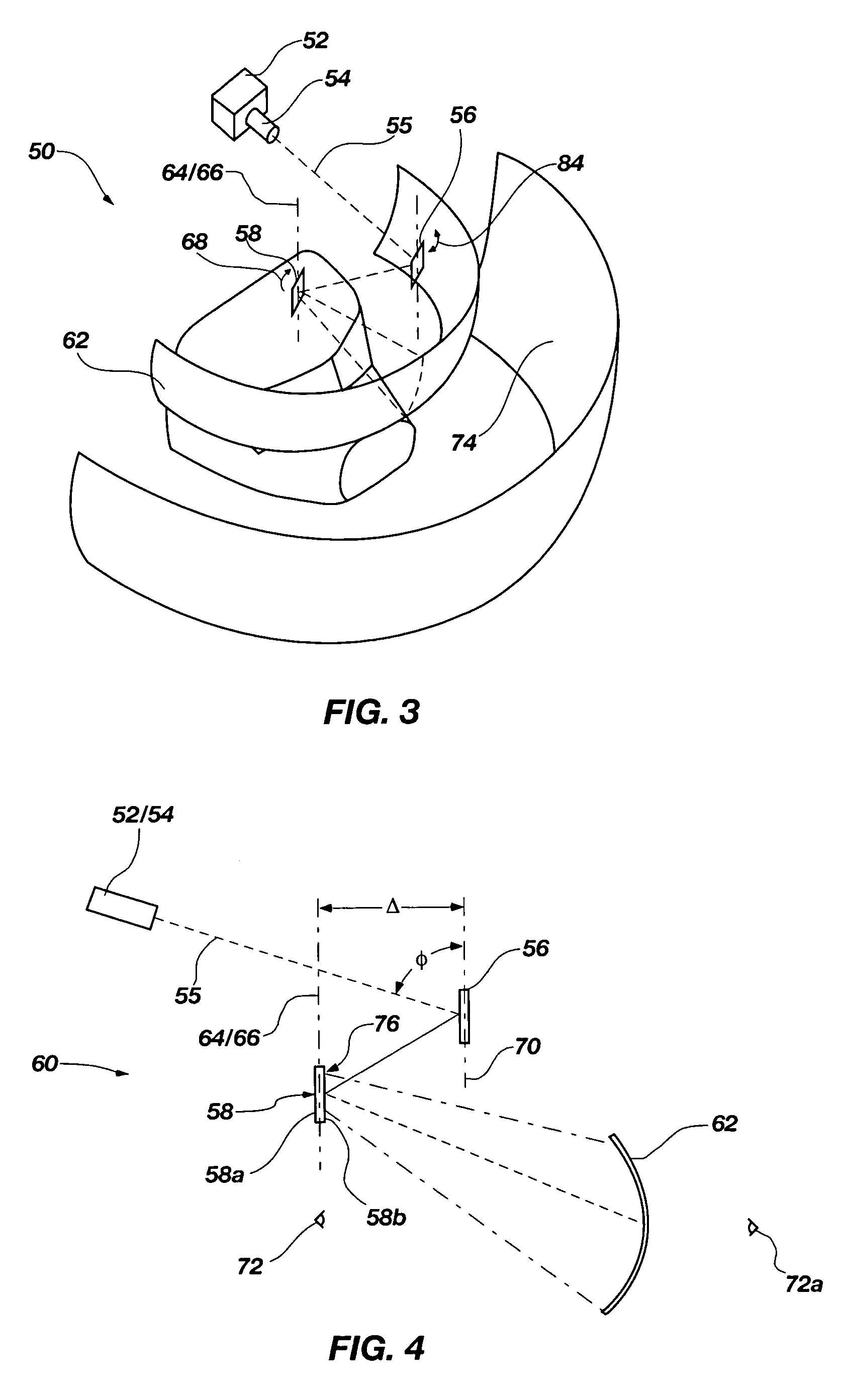
[0043]The inventors have developed a new type of laser scanner for surrounding a viewer with a panoramic image. For purposes of this discussion, the terms “panoramic image” and “panoramic display” are used to refer to a display or image in which the horizontal dimension is much greater than the vertical dimension. It will be apparent that “horizontal” and “vertical” are relative terms. They do not refer to any pa...


PUM


Abstract

A panoramic display system includes a curved projection screen, a panoramic projector, and a substantially conically shaped barrier. The projector is configured to project an image onto the projection screen from a projection point located substantially above the projection screen. The conical barrier has a base disposed toward the bottom of the projection screen, and an apex region disposed toward the projection point. The barrier blocks scattered light from reflecting from portions of the curved screen to other portions thereof.

Description

[0001]The present application is a continuation-in-part of U.S. patent application Ser. No. 10 / 642,880 filed on Aug. 18, 2003 now U.S. Pat. No. 6,871,958 and entitled WIDE ANGLE SCANNER FOR PANORAMIC DISPLAY.BACKGROUND OF THE INVENTION[0002]1. Field of the Invention[0003]The present invention relates generally to panoramic visual display systems. More particularly, the present invention relates to a barrier for reducing light scattering on a panoramic display screen.[0004]2. Related Art[0005]A panoramic display is generally considered one in which the horizontal dimension is much greater than the vertical dimension, such that the display horizontally wraps around the viewing point, at least partially. Panoramic visual display systems are desirable in a number of applications. One particular application needing wide fields of view is flight simulation and training. Heretofore, panoramic flight simulator visual display systems have typically used multiple projectors, with their separa...

Claims


Application Information

Patent Timeline
Patent Type & Authority Patents(United States)
IPC IPC(8): G03B37/00G03B21/56G03B21/28G03B21/32G06F7/00
CPCG03B37/00G03B21/32G02B27/0018H04N5/74
Inventor STREID, HARRYCHRISTENSEN, ROBTANNER, ALLEN H.
Owner EVANS & SUTHERLAND COMP
Why Eureka
Try Eureka