Thermal dissipation assembly and fabrication method for electronics drawer of a multiple-drawer electronics rack

a technology of electronics rack and electronics drawer, which is applied in the direction of lighting and heating apparatus, electrical apparatus casings/cabinets/drawers, instruments, etc., can solve the problems of failure of chip devices and increasing difficulty in dissipating heat by simple air cooling

Active Publication Date: 2006-03-14
LENOVO GLOBAL TECH INT LTD
View PDF11 Cites 227 Cited by
  • Summary
  • Abstract
  • Description
  • Claims
  • Application Information

AI Technical Summary

Problems solved by technology

Nonetheless, it is also known that runaway thermal conditions and excessive heat generated by chips is a leading cause of failure of chip devices.
The problem with this configuration is that the increase in heat flux at the electronics drawer level makes it increasingly difficult to dissipate heat by simple air cooling.

Method used


Image

  • Thermal dissipation assembly and fabrication method for electronics drawer of a multiple-drawer electronics rack
  • Thermal dissipation assembly and fabrication method for electronics drawer of a multiple-drawer electronics rack
  • Thermal dissipation assembly and fabrication method for electronics drawer of a multiple-drawer electronics rack

Examples


Embodiment Construction

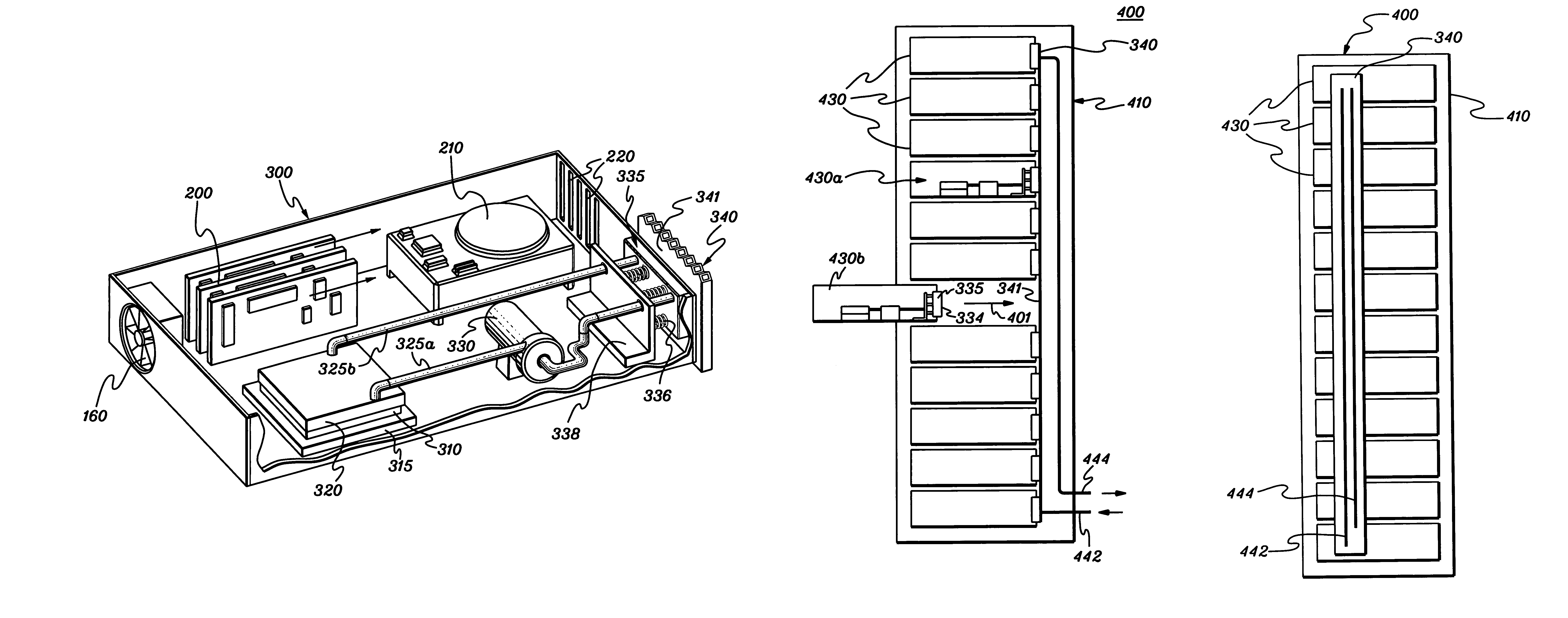
[0014]As used herein, “electronics drawer” comprises any receptacle, compartment, node, book, etc., containing one or more heat generating components of a computer system or other electronics system requiring cooling. The term “electronics module” includes any heat generating component of a computer system or electronics system and may be, for example, one or more integrated circuit devices, or one or more packaged electronics devices (such as a processor module).

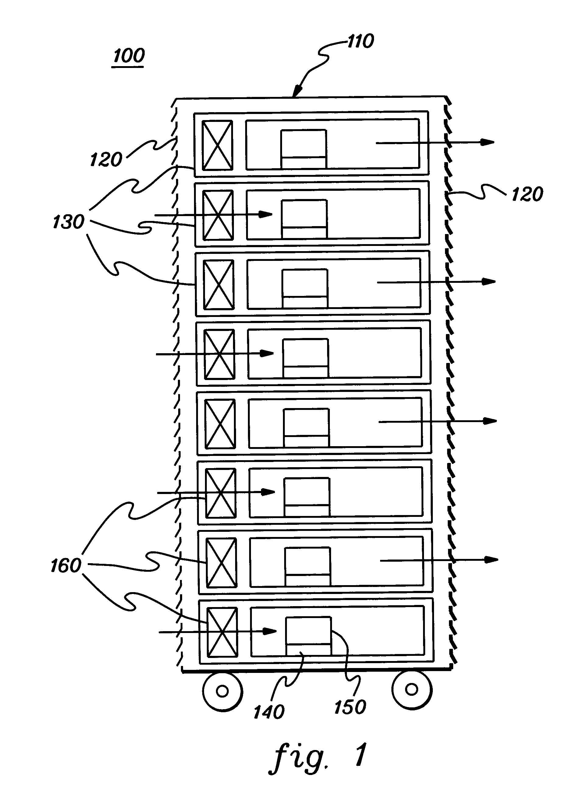
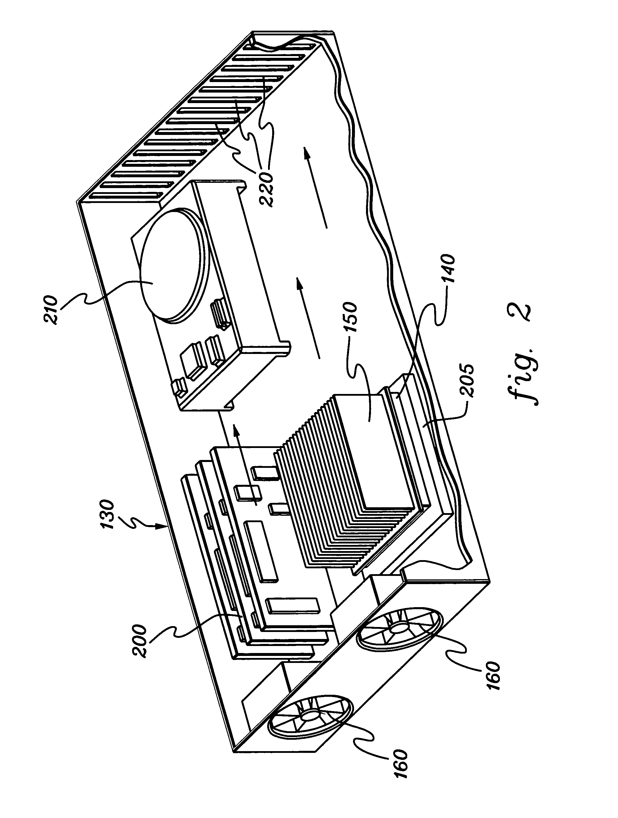
[0015]FIG. 1 depicts one embodiment of a conventional multi-drawer electronics rack, generally denoted 100. Rack 100 includes a frame or housing 110 having ventilated covers 120 over multiple sides thereof to allow for flow of air through the housing. Rack 100 also includes a plurality of electronics drawers 130, one or more of which are removable so that the electronics drawer can be readily replaced in the event of failure.

[0016]Multi-drawer electronics rack 100 is conventionally cooled by forced air flow, for example, pr...


PUM


Abstract

A thermal dissipation assembly and method, and a cooled multi-drawer electronics rack are provided having a first cooling loop and a second cooling loop. The first cooling loop is disposed substantially within an electronics drawer and positioned to extract heat from an electronics module within the drawer. The first cooling loop further includes a first planar heat transfer surface. The second cooling loop is disposed substantially external to the electronics drawer and includes a second planar heat transfer surface. A biasing mechanism mechanically forces the first planar heat transfer surface and the second heat transfer surface coplanar when the electronics drawer is in a docked position in the electronics rack to facilitate the transfer of heat from the first cooling loop to the second cooling loop.

Description

TECHNICAL FIELD[0001]The present invention is directed to cooling assemblies and other apparatus used for removing heat from electronic devices and modules. More particularly, this invention relates to an enhanced thermal dissipation assembly and fabrication method for extracting heat from a heat generating component disposed within an electronics drawer of a multi-drawer electronics rack.BACKGROUND OF THE INVENTION[0002]As is well known, as the circuit density of electronic chip devices increases in order to achieve faster and faster processing speed, there is a correspondingly increasing demand for the removal of heat generated by these devices. The increased heat demand arises both because the circuit devices are packed more closely together and because the circuits themselves are operated at increasingly higher clock frequencies. Nonetheless, it is also known that runaway thermal conditions and excessive heat generated by chips is a leading cause of failure of chip devices. Furt...

Claims


Application Information

Patent Timeline
Patent Type & Authority Patents(United States)
IPC IPC(8): H05K7/20G06F1/20
CPCG06F1/20H05K7/20772G06F2200/201
Inventor CHU, RICHARD C.ELLSWORTH, JR., MICHAEL J.SCHMIDT, ROGER R.SIMONS, ROBERT E.
Owner LENOVO GLOBAL TECH INT LTD
Why Eureka
Try Eureka