Torque sensor

a technology of torque sensor and torque detecting unit, which is applied in the direction of electrical steering, force/torque/work measurement apparatus, instruments, etc., can solve the problems of difficult to suppress the effect of external magnetic field on the torque sensor, the characteristic of the torque sensor changes, and the difficulty in performing the neutral point adjustment of the torque detection signal by the torque detecting unit as a single unit, so as to achieve stabilization of the steering feeling and reduce the uneasy steering feeling

Active Publication Date: 2006-03-21
HONDA MOTOR CO LTD
View PDF19 Cites 25 Cited by
  • Summary
  • Abstract
  • Description
  • Claims
  • Application Information

AI Technical Summary

Benefits of technology

[0024]According to the fifth torque sensor, since the torque sensor is mounted as a sensor for detecting the torque occurring in the steering system of the vehicle having the electric power steering apparatus, when the torque sen...

Problems solved by technology

However, with the conventional steering torque detecting unit, since no special magnetic shield section is provided, if a change in the external environment before and after the installation of the torque detecting unit in the vehicle is taken into consideration, there is a problem in that it is, difficult to perform the neutral point adjustment of the torque detection signal by t...

Method used


Image

  • Torque sensor
  • Torque sensor
  • Torque sensor

Examples


second embodiment

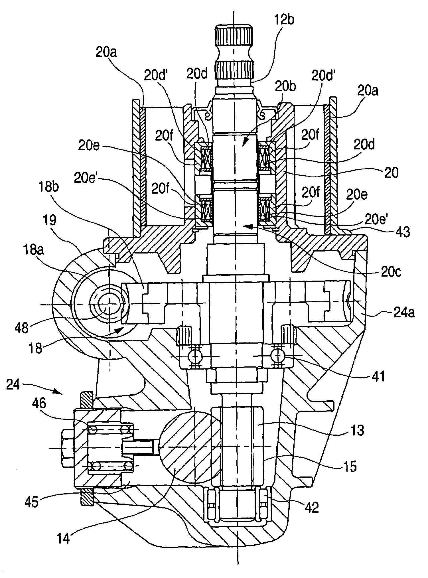
[0054]FIG. 5B is a diagram illustrating a second modification. In the second embodiment, the holding member 43 itself of the torque sensor is constructed by using such a material as satisfies the functions described in the invention, i.e., a magnetic material having a low coercive force characteristic, e.g., a silicon steel sheet. The magnetic material is one of such as 50A600–50A1300 (according to JIS C 2552). Here, the numerical value “50” is a value in which the nominal thickness (mm) is made 100-fold, and the code “A” indicates a non-oriented material, i.e., a material whose permeability is substantially fixed irrespective of the rolling direction. In addition, the numerical value “600” or “1300” is a value in which 1 (kg) equivalent weight (W / kg) of the iron loss is made 100-fold. In this case, a magnetic shield is provided by the holding member 43, and the effect of the external magnetic field can be suppressed.

third embodiment

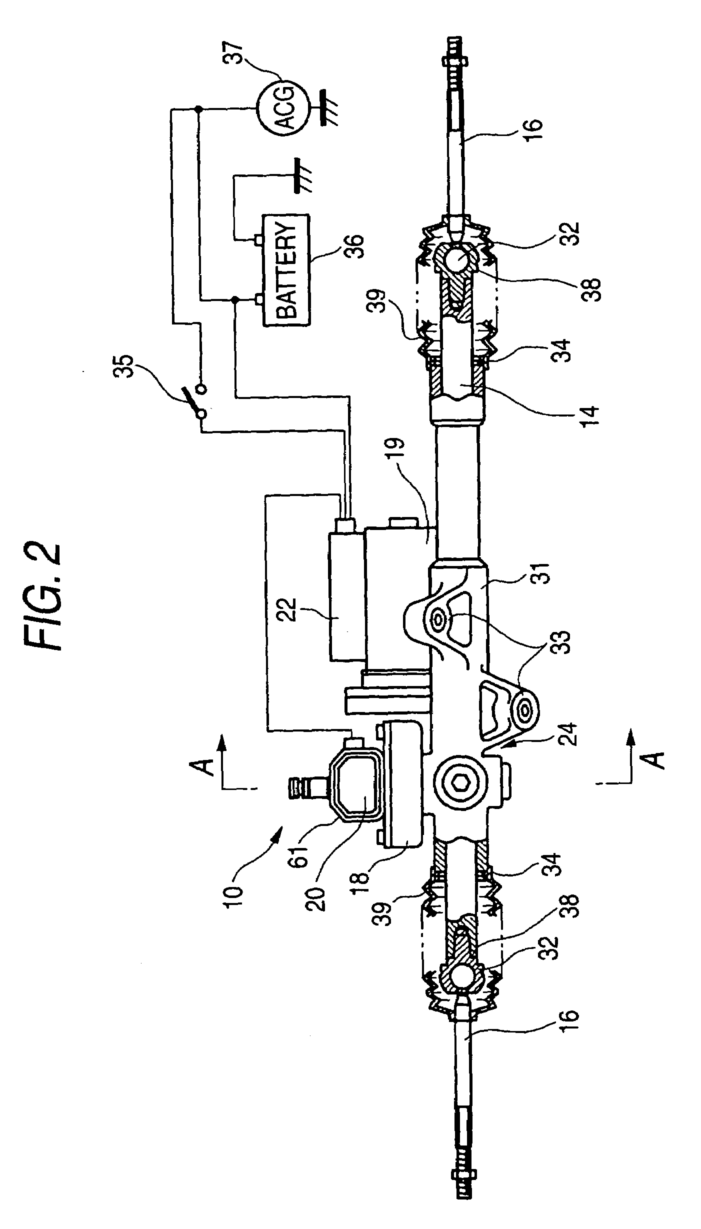
[0055]FIG. 5C is a diagram illustrating a third modification. In the third embodiment, a cover member 61 covering the entire torque sensor is constructed by using such a material as satisfies the functions described in the invention, i.e., a magnetic material having a low coercive force characteristic, e.g., a silicon steel sheet. In this case, a magnetic shield is provided by the cover member 61, and the effect of the external magnetic field can be suppressed.

[0056]It should be noted that the magnetic shield member may be provided with the function of a thermal insulation means for protecting the torque sensor from the heat generation from a high heat portion such as the engine.

[0057]As is apparent from the foregoing description, the following advantages are offered in accordance with the invention.

[0058]The magnetic shield section formed of a magnetic material is provided around the outer periphery of the yoke portion. Therefore, as the shield section formed of the magnetic materi...


PUM


Abstract

A magnetostriction-type torque sensor 20 includes a shaft 12b formed of a magnetic material and provided with at least magnetostrictive films 20b and 20c; exciting coils 20d′ and 20e′ for exciting the magnetostrictive films 20b and 20c provided on the shaft 12b; detection coils 20d and 20e for detecting a change in a magnetic field; and yoke portions 20f respectively provided around outer peripheries of the exciting coils 20d′ and 20e′ and the detection coils 20d and 20e, wherein a magnetic shield section 20a formed of a magnetic material is provided around the outer peripheries of the yoke portions 20f.

Description

BACKGROUND OF THE INVENTION[0001]The present invention relates to a torque sensor, and more particularly to a torque sensor for an electric power steering apparatus for alleviating the steering torque of a driver by causing the power of a motor to be directly applied to a steering system.[0002]An electric power steering apparatus has a motor in a steering system, and alleviates the steering torque of the driver by controlling the power supplied from the motor by using a controller. A conventional electric power steering apparatus has a steering torque detecting unit (torque sensor) provided in a steering gearbox for detecting a steering torque applied to a steering shaft coupled to a steering wheel. Its detected value is inputted to the controller, and is supplied as a reference signal for allowing the motor to generate an appropriate assist steering torque.[0003]As the above-described steering torque detecting unit, a magnetostriction type is known in addition to a torsion bar type...

Claims


Application Information

Patent Timeline
IPC IPC(8): G01L3/02G01L3/10B62D5/04G01L5/22
CPCG01L3/102G01L3/105G01L5/221
Inventor NAKAMURA, YOSHITOSHIMIZU, YASUOSUEYOSHI, SHUNICHIRO
Owner HONDA MOTOR CO LTD
Why Eureka
Try Eureka