Fuel injector

a fuel injector and fuel cloud technology, applied in the direction of fuel injection apparatus, charge feed system, combustion engine, etc., can solve the problems of increased conical cloud thickness, impeded flame path, and inability to rapid burn up of mixture cloud, etc., to achieve the effect of safe igniting of fuel cloud

Inactive Publication Date: 2006-03-21
DAIMLER AG
View PDF15 Cites 1 Cited by
  • Summary
  • Abstract
  • Description
  • Claims
  • Application Information

AI Technical Summary

Benefits of technology

[0007]In a fuel injector for a direct-injection internal combustion engine comprising an injection nozzle, on the circumference of which a plurality of injection orifices are arranged so as to line up with one another, to form an orifice arrangement for the formation of an essentially conical fuel cloud from the individual fuel jets of the respective injection orifices the nozzle orifice locations are displaced so as to form a recess in the jet envelope in an area where a spark plug is located into which the spark plug extends so as to safely ignite the fuel cloud without getting wetted by the fuel.
[0008]Preferably, in the region of the surface of the injection nozzle wherein the injection orifices forming the conical jet are disposed, further injection orifices are provided through which fuel is injected into the interior of the conical mixture cloud in a controlled manner. This results, overall, in a more uniform fuel distribution in the jet cone. In this way, the formation of zones of lean mixture within the fuel cloud is enriched, and a more rapid burn-up of the mixture cloud formed from uniformly distributed fuel is obtained.
[0009]Advantageously, the surface of the injection nozzle is spherical, with the result that the individual injection orifices direct their fuel jets into different regions within the fuel cone. In an advantageous design of the invention, at least one central injection orifice is provided in the region of a longitudinal axis of the injector, the central injection orifice preferably lying on the longitudinal axis of the nozzle. Fuel is thereby injected into that central region of the conical mixture cloud which cannot be reached by the injection orifices in the conical jet, so that, overall, the uniformity of the fuel distribution in the jet cone is promoted.
[0012]To improve the inflammability and combustion behavior of the mixture cloud, there is provision, according to the invention, in the circumferential region of the injection nozzle which corresponds to the position of a spark plug in relation to the injector at the intended installation position of the injector, for at least one injection orifice lying in this circumferential region to be designed differently from other injection orifices in terms of position and / or orifice geometry in such a way that a fuel jet having a smaller cone angle is generated. As a result, a gap in the fuel density of the cone envelope and consequently a notch-shaped indentation is formed in the conical cloud. In this way, a rich mixture can be prepared rotationally symmetrically about the longitudinal axis of the injector or of the conical jet generated by the latter and at the same time a wetting of the spark plug with fuel can be avoided if the spark plug projects into the notch region formed in the mixture envelope. A jet-managed combustion method can thereby be implemented, without harmful deposits being formed on the spark plug due to the wetting of the spark plug with the liquid fuel. Thus, ignition misfiring is counteracted and, moreover, the stress on the spark plug due to high heat shock is reduced, so that the useful life of the spark plug is increased.

Problems solved by technology

However, with conical fuel injection, a rapid burn-up of the mixture cloud is not possible by means of the known multihole injector.
Also, in the event of deposits (carbonization) in individual injection holes in the conical jet, the flame path may be impeded by too lean a mixture in the conical cloud.
Even the known arrangement of the injection holes in two rows over the circumference of the injection nozzle cannot eliminate this problem, since, at most, the thickness of the fuel-rich layer in the outer surface area of the conical cloud can be increased.

Method used


Image

  • Fuel injector
  • Fuel injector
  • Fuel injector

Examples


Embodiment Construction

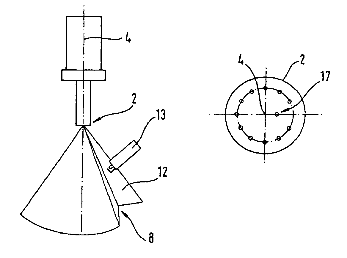
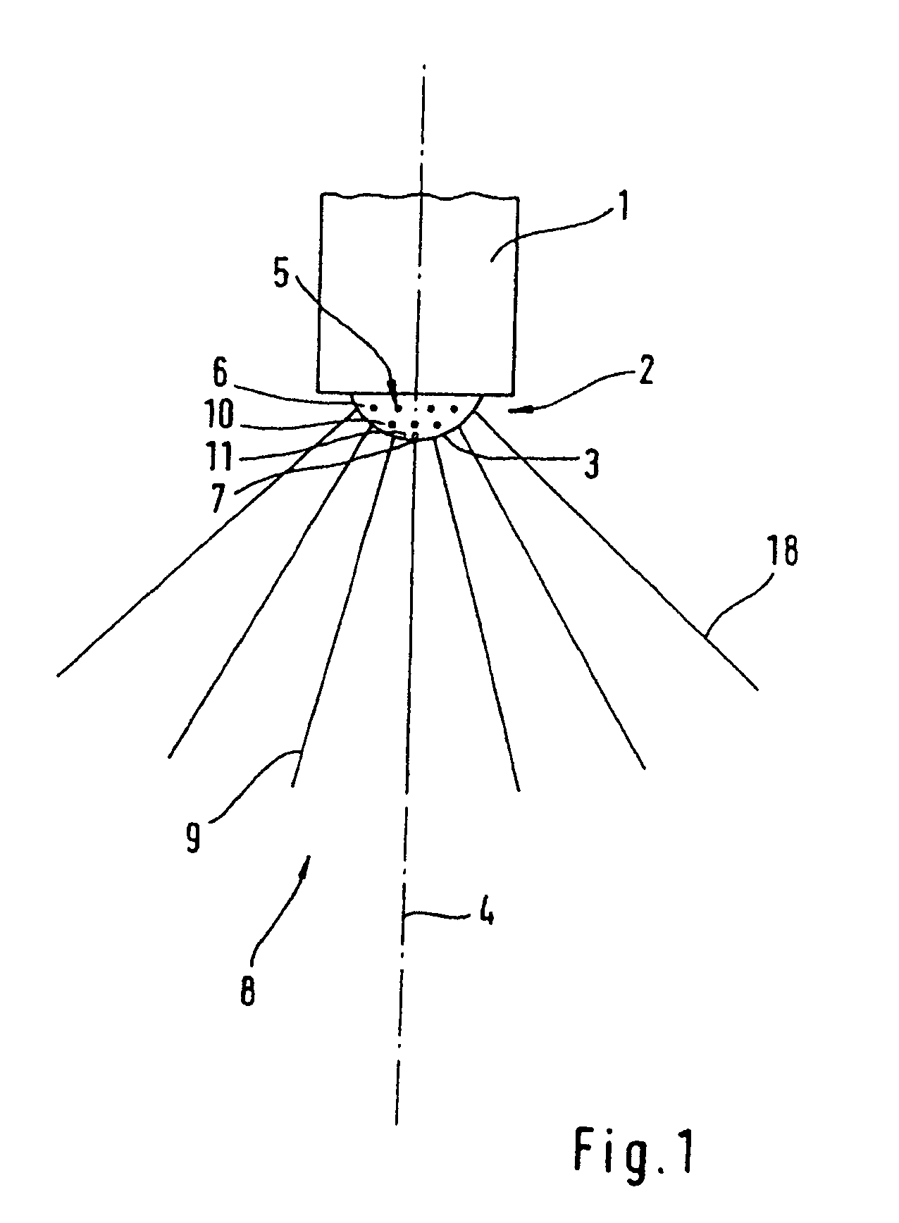
[0021]FIG. 1 shows a fuel injector 1 for a direct-injection spark-ignition internal combustion engine, said fuel injector has an injection nozzle 2 provided with a plurality of injection orifices 5. For injection, a nozzle needle, not illustrated here, is moved piezoelectrically inside the injector 1 and builds up inside the injection nozzle 2 an excess fuel pressure fuel which forces the fuel through the injection orifices 5 into the combustion space. The injection pressure may in this case amount to about 250 bar, depending on the operating point of the internal combustion engine. The surface 3 of the injection nozzle 2 is shaped spherically and, in the exemplary embodiment shown, has approximately the contour of a hemisphere. The injection orifices 5 are distributed essentially uniformly on the circumference of the spherical injection nozzle 2, the fuel jets 9 of the individual injection orifices 5 together forming a conical jet 8. The conical jet 8 is in this case generated esse...


PUM


Abstract

In a fuel injector for a direct-injection internal combustion engine comprising an injection nozzle, on the circumference of which a plurality of injection orifices are arranged so as to line up with one another, to form an orifice arrangement for the formation of an essentially conical fuel cloud from the individual fuel jets of the respective injection orifices the nozzle orifice locations are displaced so as to form a recess in the jet envelope in an area where a spark plug is located into which the spark plug extends so as to safely ignite the fuel cloud without getting wetted by the fuel.

Description

[0001]This is a Continuation-In-Part Application of International Application PCT / EP2003 / 007909 filed Jul. 19, 2003 and claiming the priority of German application 102 36 662.5 filed Aug. 9, 2002.BACKGROUND OF THE INVENTION[0002]The invention relates to a fuel injector for a direct-injection spark-ignition internal combustion engine wherein the injector is provided with a plurality of nozzle openings arranged such that the fuel discharged therefrom forms a spray cone generating a fuel cloud.[0003]In spark-ignition combustion engines, an inflammable fuel / air mixture is to be provided in the combustion space at the point of ignition at least in the region of the spark plug. It is known to inject fuel into a combustion chamber to form a fuel cloud in the region of the spark plug during low load engine operation. The cloud is formed only in the region of the spark plug and the engine thus can be operated with lower fuel consumption. For controlled fuel injection with a view to a control...

Claims


Application Information

Patent Timeline
Patent Type & Authority Patents(United States)
IPC IPC(8): F02B5/00F02M51/06F02M61/18
CPCF02M61/182F02M51/0603
Inventor GANZ, BENEDIKTGAUDRY, JEAN-FRANCOISHARTMANN, HANSKLENK, ROLFMLEJNEK, ANDREASROBLER, KLAUSSCHEFFEL, HELMUTSTRUBEL, DIRKZAHN, MATTHIAS
Owner DAIMLER AG
Why Eureka
Try Eureka