Striking and open lamp regulation for CCFL controller

a technology of open lamp and inverter controller, which is applied in the direction of electric variable regulation, process and machine control, instruments, etc., can solve the problems of limited power required to generate light, and achieve the effects of maximizing secondary voltage, improving loop stability, and facilitating control and compensation

Inactive Publication Date: 2009-08-04
MICROSEMI CORP
View PDF382 Cites 1 Cited by
  • Summary
  • Abstract
  • Description
  • Claims
  • Application Information

AI Technical Summary

Benefits of technology

[0010]In one embodiment, a method of igniting a lamp (e.g., a fluorescent lamp) includes sequentially controlling a duty cycle sweep and a frequency sweep in a pulse width modulation (PWM) controller to provide an increasing output voltage to the lamp. For example, the method controls both parameters (duty cycle and frequency) in a novel manner for lamp ignition and open lamp voltage regulation. The method allows for seamless operation of ignition and open lamp voltage regulation schemes during a strike mode of the PWM controller.
[0012]The method also provides accurate (or improved) regulation of open lamp voltage (e.g., when lamp is missing during the strike mode). In one embodiment, the ignition scheme works in conjunction with the open lamp voltage regulation scheme. For example, if the lamp is not present or defective during the strike mode, the PWM controller regulates the secondary voltage to prevent damage to the secondary winding. The open lamp voltage regulation scheme advantageously controls (or limits) the secondary voltage to a window (or range) of secondary voltages that are sufficient to ignite a lamp without causing damage to the secondary winding. The open lamp voltage regulation scheme reduces overshoot in the secondary voltage and regulates the secondary voltage over a wide range of variables. For example, the open lamp peak voltage regulation is specified to be within five percent in one embodiment.
[0013]In one embodiment, the invention is used in notebook or laptop computer backlighting applications in which duty cycle and frequency vary over a wide range for lamp ignition and open lamp voltage regulation. The invention also applies to television, automotive and other applications that use backlighting for visual displays. The invention advantageously controls both duty cycle and frequency in a stable closed feedback loop (e.g., with minimal overshoot in the secondary voltage). A combination of duty cycle control and frequency control provides flexibility to generate a secondary voltage sufficient to strike the lamp without exceeding a maximum rating of the secondary winding in applications with different lamps, transformers, printed circuit board layouts, battery voltages, etc. For example, the invention ensures that a striking frequency is not too low or too high, a duty cycle is not too low for relatively lower battery voltages or too high for relatively higher battery voltages, or open lamp voltage does not exceed secondary voltage ratings.
[0017]In one embodiment of the invention, a controller changes the duty cycle of a driving signal during a first stage of a strike mode and changes the frequency of the driving signal during a second stage of the strike mode to ignite a CCFL. The adjustment of the duty cycle (e.g., from a minimum to a maximum duty cycle) followed by adjustment of the frequency (e.g., from a lower frequency to a higher frequency), as needed, has many advantages. First, closed loop regulation (e.g., open lamp voltage regulation) is easier to control and compensate since the initial stage of changing (or sweeping) the duty cycle does not change the closed loop gain. Second, loop stability improves by maximizing the secondary voltage at the lower frequency which is achieved by sweeping the duty cycle to a maximum duty cycle before sweeping the frequency. As the frequency increases toward a resonant frequency, the closed loop gain changes rapidly. The closed loop gain does not change dramatically at lower frequencies away from the resonant frequency. Thus, maximizing the secondary voltage at a low frequency provides loop stability which leads to a more stable open lamp voltage regulation. Third, sweeping the duty cycle first is helpful in applications with relatively high battery voltages in which a relatively lower duty cycle is sufficient to strike the CCFL and a relatively high duty cycle may cause the secondary voltage to exceed a specification for a maximum open lamp voltage. Fourth, transformer saturation (in which the primary winding appears as a short circuit) can be avoided by sweeping the duty cycle from the minimum to the maximum duty cycle. This method of duty cycle sweeping allows the CCFL to safely ignite at a relatively lower duty cycle before reaching transformer saturation. Transformer saturation depends on a product of the battery voltage and the driving signal pulse width.
[0018]In another embodiment of the invention, a controller changes the frequency of a driving signal during a first stage of a strike mode and changes the duty cycle of the driving signal during a second stage of the strike mode to ignite a CCFL. The sequence of sweeping the frequency first and then sweeping the duty cycle also has advantages. For example, a transformer is capable of more power transfer at relatively higher frequencies. In some applications using an under-designed transformer, the transformer may saturate when operating at a relatively low frequency and a high duty cycle. Thus, one striking sequence sweeps the driving signal from a relatively low frequency to a relatively high frequency at a relatively low duty cycle first and then, as needed, sweeps the driving signal from the relatively low duty cycle to a relatively high duty cycle at the relatively high frequency. Starting with a low, but fixed, duty cycle driving signal and sweeping the frequency of the driving signal first is a safer way to prevent transformer saturation since higher frequency operation reduces the danger of saturation, especially in applications without feed forward circuits that limit duty cycle as a function of the battery voltage.

Problems solved by technology

Fluorescent lamps are used in a number of applications where light is required but the power required to generate the light is limited.

Method used


Image

  • Striking and open lamp regulation for CCFL controller
  • Striking and open lamp regulation for CCFL controller
  • Striking and open lamp regulation for CCFL controller

Examples


Embodiment Construction

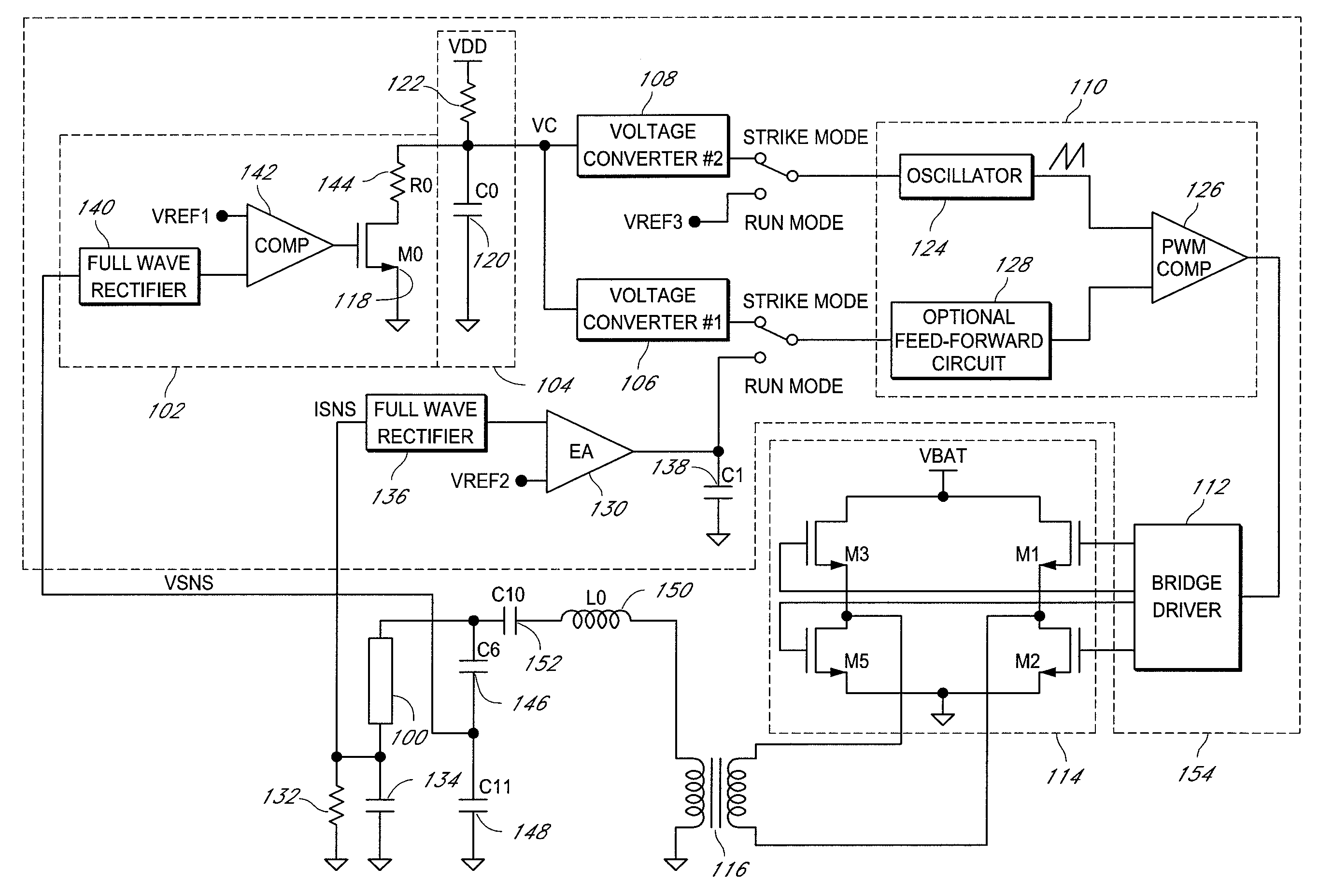
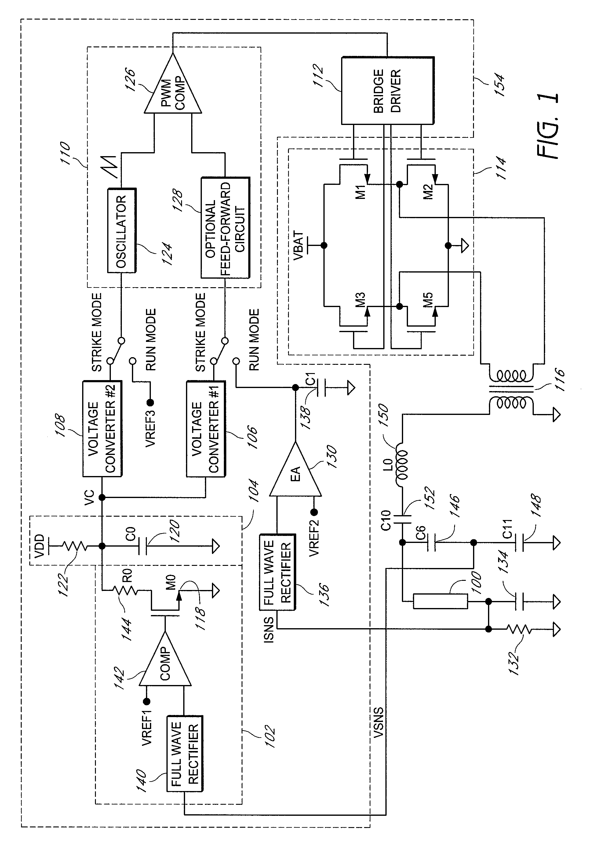
[0025]Further descriptions of several embodiments of the invention will be described hereinafter with reference to the drawings. FIG. 1 illustrates a circuit block diagram of one embodiment of an inverter for powering a lamp (e.g., a CCFL) 100. The inverter comprises a closed feedback loop that seamlessly controls ignition of the lamp 100 and provides open lamp voltage regulation during a strike mode of the inverter. In one embodiment, the closed feedback loop comprises a voltage detector circuit 102, a control voltage generator 104, a first voltage converter 106, and a second voltage converter 108.

[0026]For example, the voltage detector circuit 102 receives a first feedback signal (VSNS) indicative of an output voltage (or a voltage across the lamp 100) and generates an output indicating when the output voltage is greater than a predetermined voltage level corresponding to a first reference voltage (VREF1). The control voltage generator 104 generates a control voltage (VC) that can...


PUM


Abstract

An apparatus and method for igniting a lamp during a strike mode of an inverter comprising: sequentially controlling a duty cycle sweep and a frequency sweep of driving signals in the inverter to provide an increasing output voltage to the lamp. One embodiment advantageously includes a closed feedback loop to implement the duty cycle sweep and the frequency sweep such that an open lamp voltage is reliably regulated during the strike mode. For example, the closed feedback loop stops the duty cycle sweep or the frequency sweep when the output voltage to the lamp reaches a predetermined threshold and makes adjustments to the duty cycle or frequency the driving signals as needed to keep the output voltage at approximately the predetermined threshold if the lamp has not ignited.

Description

CLAIM FOR PRIORITY[0001]This application claims the benefit of priority under 35 U.S.C. § 119(e) of U.S. Provisional Application No. 60 / 806,714 filed on Jul. 6, 2006 and entitled “Striking and Open Lamp Regulation for CCFL Controller,” U.S. Provisional Application No. 60 / 849,211 filed on Oct. 4, 2006 and entitled “Compensation for Supply Voltage Variations in a PWM,” and U.S. Provisional Application No. 60 / 849,254 filed on Oct. 4, 2006 and entitled “PWM Duty Cycle Inverse Adjustment Circuit,” each of which is incorporated herein in its entirety by reference.BACKGROUND OF THE INVENTION[0002]1. Field of the Invention[0003]This invention relates to inverter controllers for controlling power to fluorescent lamps and more particularly to an inverter controller with reliable lamp ignition and open lamp voltage regulation.[0004]2. Description of the Related Art[0005]Fluorescent lamps are used in a number of applications where light is required but the power required to generate the light i...

Claims


Application Information

Patent Timeline
Patent Type & Authority Patents(United States)
IPC IPC(8): G05F1/00
CPCH05B41/2828H05B41/382Y02B20/00
Inventor HENRY, GEORGE C.LACOMBE, DAVID K.
Owner MICROSEMI CORP
Why Eureka
Try Eureka