Micro-pilot for gas appliance

a gas appliance and micro-pilot technology, applied in the direction of combustion ignition, lighting and heating apparatus, combustion process, etc., can solve the problems of large explosion and household fire, and achieve the effects of reducing greenhouse gas emissions, saving energy, and saving energy

Inactive Publication Date: 2013-06-04
INVENSYS CONTROLS AUSTRALIA
View PDF114 Cites 2 Cited by
  • Summary
  • Abstract
  • Description
  • Claims
  • Application Information

AI Technical Summary

Benefits of technology

[0012]In view of the above, embodiments of the present invention provide a new and improved energy saving pilot for a hot water heater or other gas burning appliance. More particularly, embodiments of the present invention provide a new and improved pilot for a hot water heater or other gas burning appliance that not only saves energy and reduces greenhouse gas emissions, but also ensure ignition of the main burner and safe ignition of flammable vapor.
[0013]In one embodiment, the invention utilizes bleed gas from a safety relay valve to increase the size of the pilot flame just prior to opening a main flow of gas to the burner from a micro-pilot flame size to an ignition flame size when the hot water heater's main combination gas controller calls for heat. This allows for a smaller amount of gas to be used for the pilot to operate it as a micro-pilot during the periods when the burner is off with no call for heat and will ensure ignition of the main gas flow to the burner when a call for heat has been issued. The smaller or micro-pilot flame will also provide smoother ignition of gasoline fumes in Flammable Vapor Resistant heaters.
[0014]In another embodiment, the invention utilizes a physically separate micro-pilot and a booster or ignition pilot that is operated from bleed gas from a safety relay valve. The bypass gas flow to the booster pilot will occur just prior to opening the main flow of gas to the burner. The micro-pilot flame will ignite the booster pilot supplied with the bypass gas, which will then ignite the main gas flow to the burner. This allows for a smaller amount of gas to be used for the pilot to operate it as a micro-pilot during the periods when the burner is not on and will ensure ignition of the main gas flow to the burner when a call for heat has been issued. The smaller or micro-pilot flame will also provide smoother ignition of gasoline fumes in Flammable Vapor Resistant heaters.
[0015]In each embodiment, the micro-pilot is sized to be large enough to provide enough heat to the safety thermocouple to keep the gas pilot safety valve open in a typical hot water heater or other gas burning appliance combination gas controller. It is also sized to be large enough to resist air turbulence due to ignition and combustion of the natural gas from the main burner. Embodiments of the present invention are also positioned so that smooth ignition results to the main burner and to any flammable vapor. Rough ignition of flammable vapor will normally result in a small explosion in the combustion chamber forcing the flame front through the flame trap, possibly igniting the gasoline outside the water heater which could result in a larger explosion and a household fire. Embodiments of the present invention position the pilot flame for ignition relatively closer to the burner for low NOx burners to obtain smooth ignition.
[0016]Using bleed gas to boost the pilot size or to supply a booster pilot just prior to ignition of the main burner in accordance with embodiments of the present invention gives improved performance on ignition and saves gas. It allows the potential to reduce the normal size of the pilot size by way of example only approximately 50% thus saving around 4.8 Mj / day (4500 Btu / day) energy.

Problems solved by technology

Rough ignition of flammable vapor will normally result in a small explosion in the combustion chamber forcing the flame front through the flame trap, possibly igniting the gasoline outside the water heater which could result in a larger explosion and a household fire.

Method used


Image

  • Micro-pilot for gas appliance
  • Micro-pilot for gas appliance
  • Micro-pilot for gas appliance

Examples


Embodiment Construction

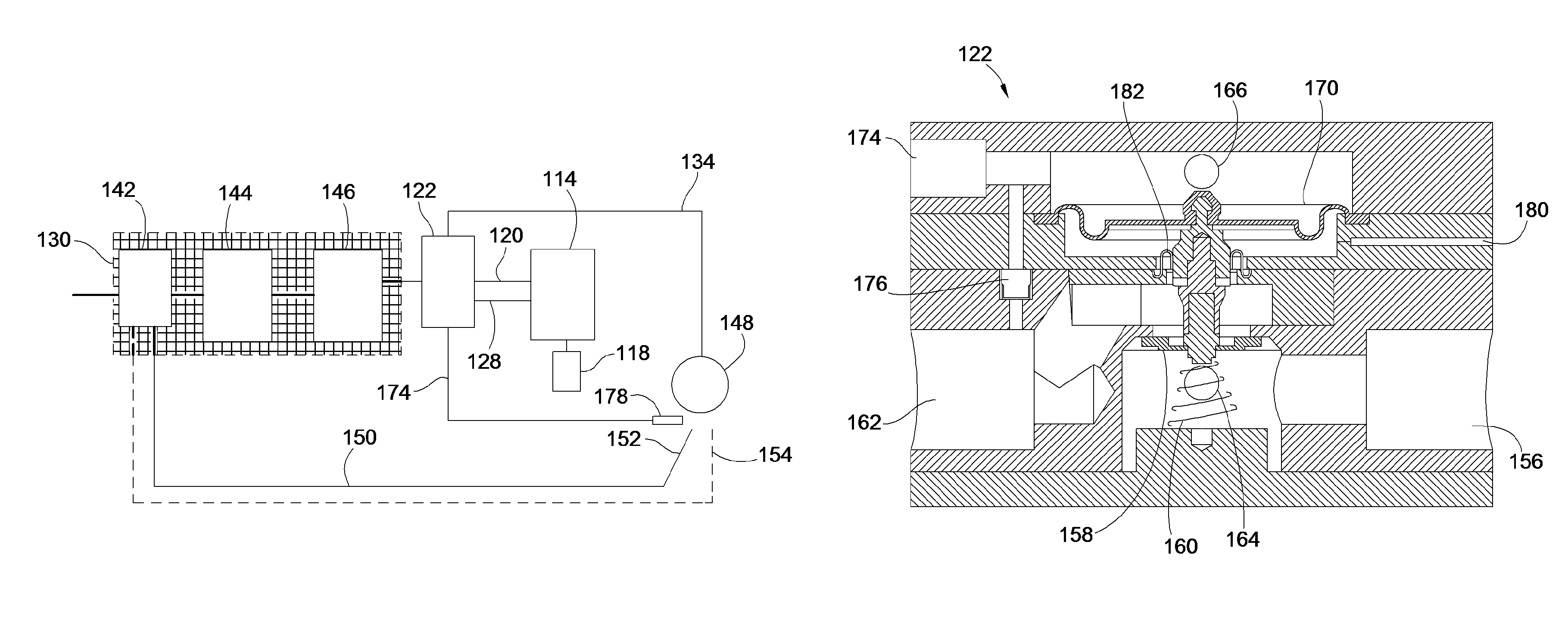
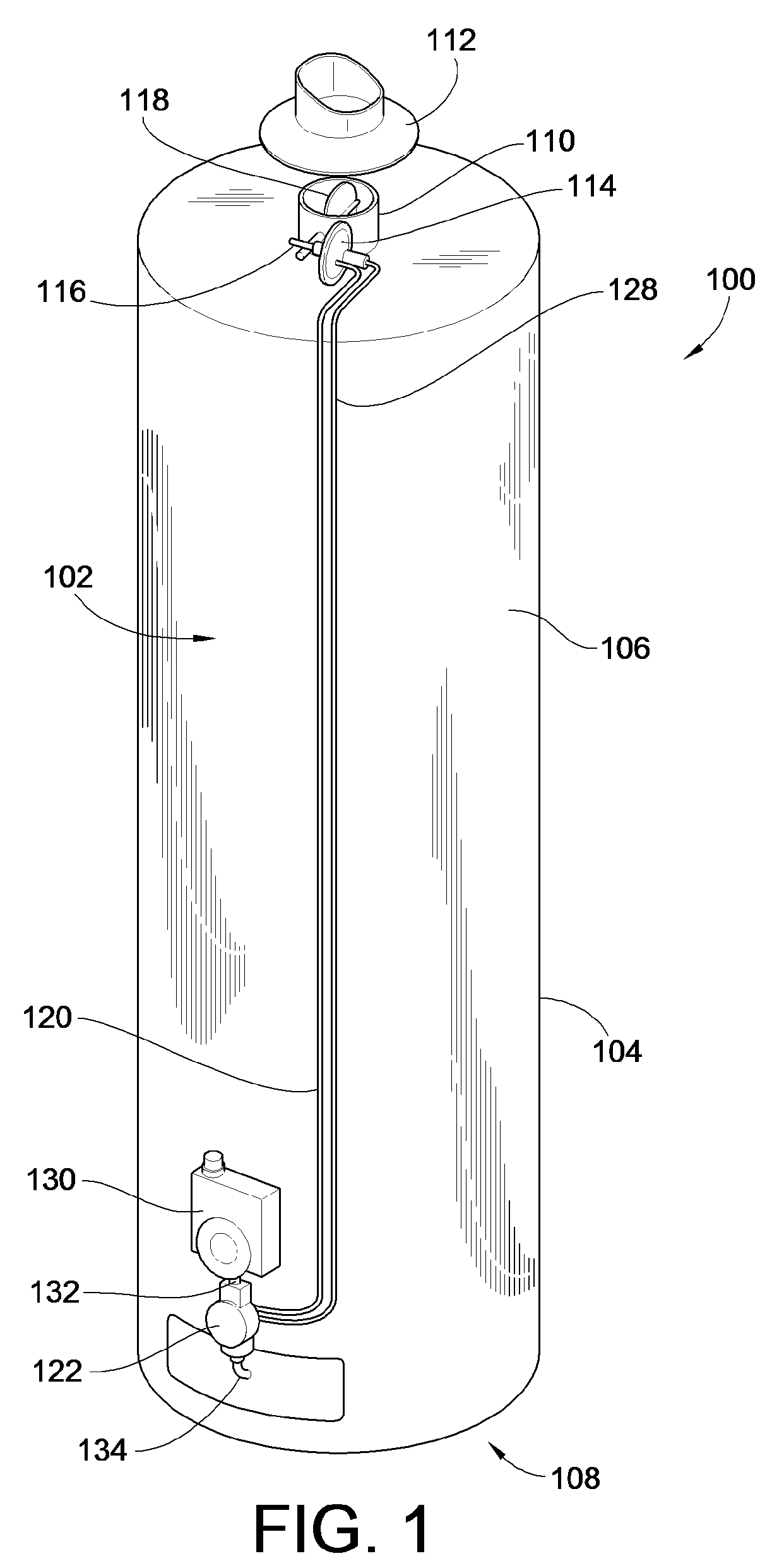
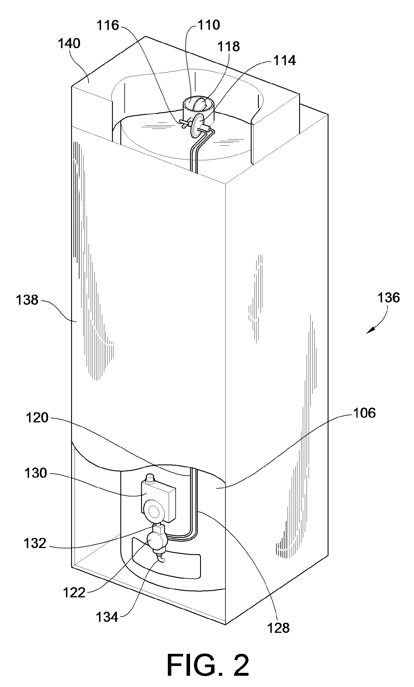
[0030]Turning now to the drawings, there is illustrated in FIG. 1 an indoor hot water heater 100 such as typically installed in dwellings in the North American market and to which embodiments of the micro-pilot system of the present invention provide particular benefit. The illustrated hot water heater includes a standby heat loss control system 102, such as that described in co-pending application Ser. No. 12 / 175,551, entitled SYSTEM AND METHOD TO REDUCE STANDBY ENERGY LOSS IN A GAS WATER HEATER, filed on Jul. 18, 2008 and assigned to the assignee of the instant application, the teachings and disclosure of which are hereby incorporated in their entireties by reference thereto. However, as will be discussed more fully below, embodiments of the present invention provide benefit to hot water heaters and other gas burning appliances that do not include such a standby heat loss control system as well. Indeed, it should be noted that while the following description will discuss various e...


PUM


Abstract

A micro pilot for a gas hot water heater is provided. The micro pilot provides a flame that is substantially smaller than a typical pilot in a hot water heater during standby operation of the burner. Just prior to allowing gas to flow to the burner upon a call for heat, a pilot flame of sufficient size to ensure ignition of the burner is provided. In one embodiment this larger pilot flame is produced by providing an additional amount of bleed gas to the pilot to increase flame size. In another embodiment, bleed gas is provided to a separate booster pilot, which is ignited by the micro pilot. The flame from the booster pilot is then used to ignite the main burner. This design allows for the micro pilot to be positioned closer to the flame trap of a flammable vapor resistant hot water heater to ensure smooth ignition of any such vapor.

Description

FIELD OF THE INVENTION[0001]This invention generally relates to energy conservation systems, and more particularly to energy conservation systems to be employed with gas burning appliances to reduce the amount of gas used by a pilot while ensuring proper burner and flammable vapor ignition.BACKGROUND OF THE INVENTION[0002]It has now been recognized that the world's environment is suffering too much from global warming caused by greenhouse gas exposure in the atmosphere. To address this problem governments are now starting to adopt targets for reducing the emission of greenhouse gases to the environment and play their part to address this problem for future generations. While some countries have not adopted a firm goal, other countries, for example Australia, have adopted a policy for the reducing greenhouse gases by 20% by the year 2020.[0003]Greenhouse gases can be emitted from cars, industry, farming, and households to name a few. While certainly not as apparent as a large factory...

Claims


Application Information

Patent Timeline
Patent Type & Authority Patents(United States)
IPC IPC(8): F23Q9/08
CPCF23N5/242F24H1/186F24H9/2035F23C2900/03001F23N2027/02F23N2027/22F23N2031/08F23N2035/20F23N2037/12F23N2041/04F23N2900/01001F23N2227/02F23N2231/08F23N2227/22F23N2237/12F23N2241/04F23N2235/20F24H15/156F24H15/33F24H15/223F24H15/174F24H15/31
Inventor WHITFORD, GEOFFREY MERVYNRUWOLDT, BRENDON JOHN
Owner INVENSYS CONTROLS AUSTRALIA
Why Eureka
Try Eureka