Method for introducing microwave energy into a combustion chamber of a combustion engine and combustion engine

a combustion engine and combustion engine technology, applied in the direction of engine ignition, electrical equipment, plasma technique, etc., can solve problems such as efficiency degradation, and achieve the effects of improving efficiency, facilitating precise control of the beginning, and low emission combustion

Inactive Publication Date: 2018-05-01
MWI MICRO WAVE IGNITION
View PDF22 Cites 0 Cited by
  • Summary
  • Abstract
  • Description
  • Claims
  • Application Information

AI Technical Summary

Benefits of technology

[0013]Advantageously the microwaves are conducted at an end of the annular hollow conductor cavity into the combustion chamber at an angle in order to prevent reflections of the microwaves that have already run around the combustion chamber at an end of the annular conductor cavity back to a microwave source or in order to at least substantially mitigate those reflections.
[0016]It is furthermore advantageous when the microwaves are introduced in impulse packets wherein the impulse packets are advantageously also maintained after an ignition of a fuel air mixture that has already been performed. Thus, the ignition of the fuel air mixture is optimized and the combustion of the fuel air mixture is further excited even after the ignition has already been performed and the combustion chamber may already be expanding.
[0017]It is a particular advantage of the method that the microwaves are introduced as function of crank shaft angle degrees so that a precise control of the ignition can be performed.
[0030]Therefore a slightly different period of the openings is selected as an alternative according to the invention. Thus, the face fronts are inclined. The power propagates in a spiral shape into the combustion cavity which facilitates a high path length and thus an absorption of the microwave power that is largely independent from tan δ. The width of the openings is varied so that the power injected into the combustion chamber is constant along the circumference
[0036]The method and the combustion engine thus facilitate precise control of a beginning of a space ignition of a fuel air mixture in a combustion chamber so that an optimum low emission combustion of the fuel is achieved with increased efficiency compared to conventional reciprocating piston internal combustion engines. Typically the invention facilitates safe ignition of lean fuel air mixtures which does not require additional enrichment for achieving ignition and which leads to a lower fuel consumption. Emissions and their generation can be controlled by the combustion temperature and the mix ratio of air and fuel. Combustion according to the invention occurs faster than for conventional ignitions. This causes “colder” combustion so that the efficiency increases. Furthermore lower pollutant emissions are achievable through colder combustion processes as a matter of principle. The colder combustion reduces the concentration of NO in the exhaust gases. Through space ignition the combustion process, differently from conventional combustion, is much less dependent on combustion progress in the form of diffusion flames. This helps to avoid additional heat losses and achieves an efficiency increase. A heat up phase of the combustion chamber and of the air in the oxidation portion is not provided for this type of combustion.

Problems solved by technology

When both fronts meet the reaction can die down which degrades efficiency and causes pollutants.

Method used


Image

  • Method for introducing microwave energy into a combustion chamber of a combustion engine and combustion engine
  • Method for introducing microwave energy into a combustion chamber of a combustion engine and combustion engine
  • Method for introducing microwave energy into a combustion chamber of a combustion engine and combustion engine

Examples


Embodiment Construction

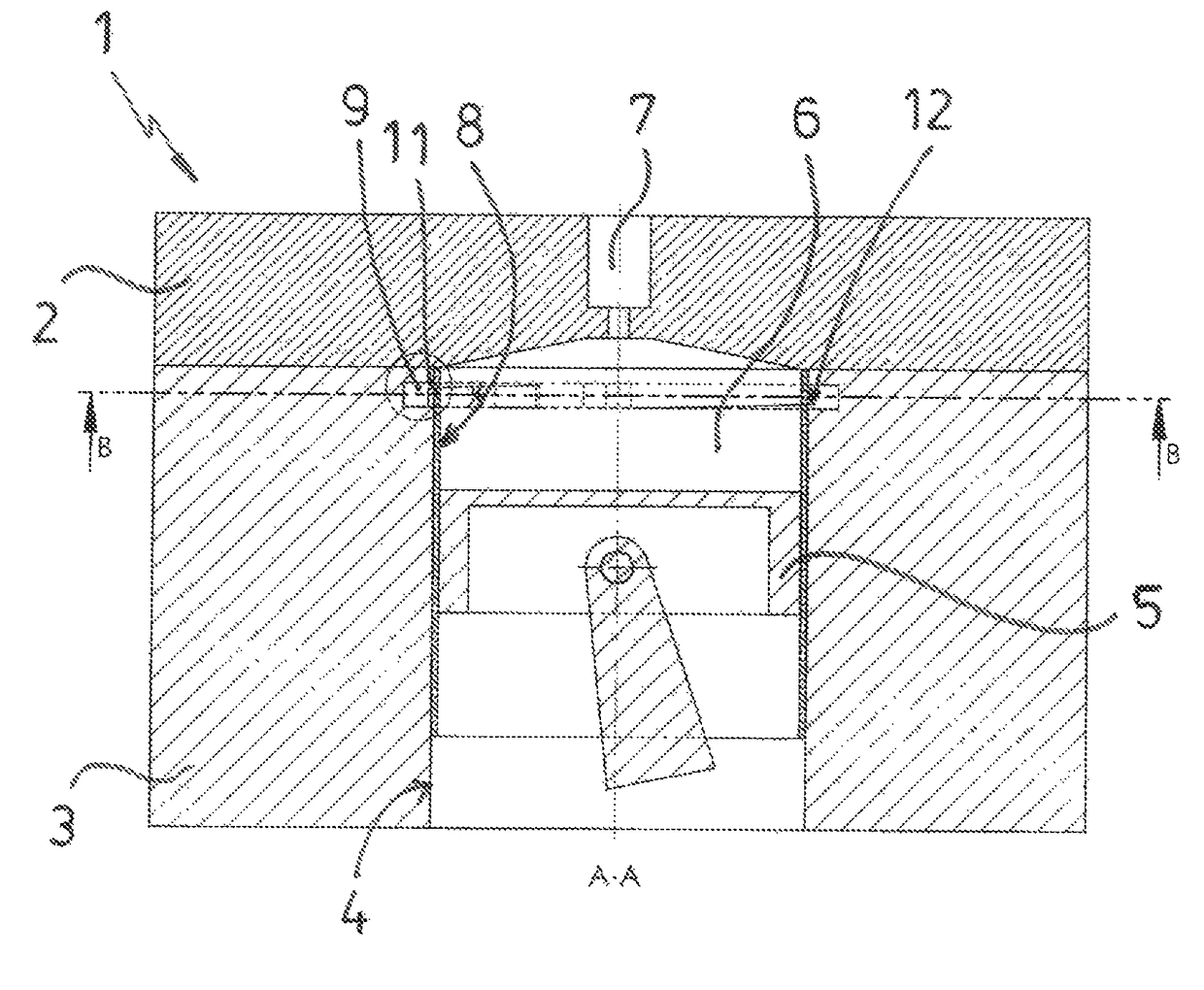
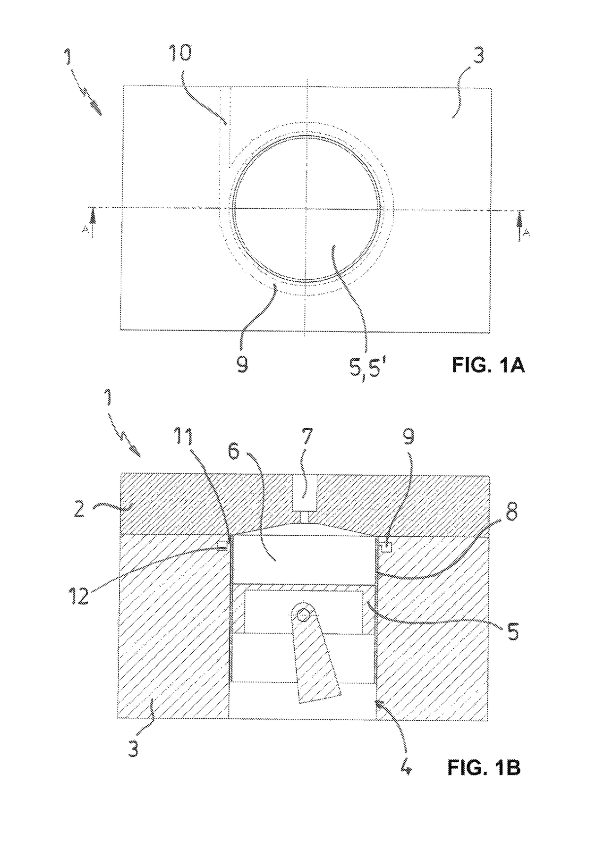
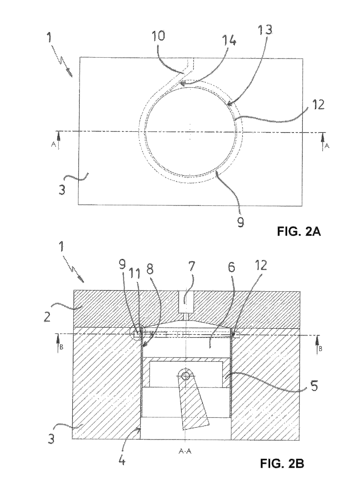
[0046]In the subsequently described figures the invention is illustrated in an exemplary manner based on various embodiments. Identical or like elements in the individual figures are provided with identical reference numerals.

[0047]The figures illustrate a schematic detail of an internal combustion engine 1 with a cylinder head 2 and an engine block 3. The engine block 3 includes a cylinder 4 with a piston 5 that is moveable therein and a combustion chamber 6 partially arranged in the cylinder head 2 above the cylinder 4. A schematically indicated inlet 7 for the fuel air mix leads into the combustion chamber 6. Outlets for the exhaust gas are not illustrated since the outlets can be configured in ways that are well known to a person skilled in the art. The schematically indicated cylinder head 2 with a central inlet 7 for the fuel air mixture can certainly also have additional spark plugs or outlets for the exhaust gases. The spark plugs can be particularly configured microwave spa...


PUM


Abstract

A method for introducing microwave energy into a combustion chamber of a reciprocating internal combustion engine with at least one cylinder with a cylinder head in which the microwaves reach the combustion chamber through a microwave window, wherein the microwaves are run about a circumference of the combustion chamber and radially injected into the combustion chamber through at least a portion of a combustion chamber wall functioning as a microwave window. The method and the internal combustion engine facilitate a precise control of a beginning of a space ignition of a fuel air mix in the combustion chamber so that an optimum low emission combustion of a fuel is achieved with an efficiency that is higher compared to conventional reciprocating piston combustion engines. In general the invention provides safe ignition of lean fuel air mixtures.

Description

RELATED APPLICATIONS[0001]This application claims priority from and incorporates by reference European Patent Application 15 157 324.3 filed on Mar. 3, 2015.FIELD OF THE INVENTION[0002]The invention relates to a method for introducing microwave energy into a combustion chamber of a reciprocating piston internal combustion engine including at least one cylinder with a cylinder head in which the microwaves are introduced into the combustion chamber. The invention also relates to an internal combustion engine.BACKGROUND OF THE INVENTION[0003]DE 103 56 916 A1 discloses to generate a space ignition in a combustion chamber in an internal combustion engine in order to better ignite and combust a fuel air mixture of an introduced fuel.[0004]In conventional engines an ignitable mixture is compressed in a cone shaped cylinder head and caused by a spark plug to react to and oxidize. Thus, a chemical oxidation spreads cone shaped from an ignition location as a pressure and reaction front (lamin...

Claims


Application Information

Patent Timeline
Patent Type & Authority Patents(United States)
IPC IPC(8): F02P23/00F02P23/04F02F1/24H05H1/46
CPCF02P23/045F02F1/24H05H2001/463F02P15/02H05H1/463F02B1/12F02M27/04Y02T10/12
Inventor GALLATZ, ARMINGALLATZ, VOLKER
Owner MWI MICRO WAVE IGNITION
Why Eureka
Try Eureka