Optical Power Beaming to Electrically Powered Devices

a technology of optical transmission and electrical power, applied in the direction of optical radiation measurement, discharge tube/lamp details, instruments, etc., can solve the problems of insufficient outlets for all devices requiring power, cords can get tangled or become trip hazards, etc., to achieve convenient and aesthetic value, safe supply of power without cords or cables, and reduce the congestion of wall outlets

Inactive Publication Date: 2010-01-21
GRAHAM DAVID S
View PDF10 Cites 106 Cited by
  • Summary
  • Abstract
  • Description
  • Claims
  • Application Information

AI Technical Summary

Benefits of technology

[0023]The optical power beaming system can reduce or eliminate the danger that a human will be harmed by entering the beam path or by receiving stray reflections generated from surfaces of system components or contaminants within the system. In one embodiment, the power beaming system includes: (1) a beam guard to prevent humans and other objects from contacting the optical power beam directly; (2) a transmitter assembly and optical-to-electric power converter that are designed to reduce reflections outside of beam path by using a diffusion layer, a baffle and / or a retroreflector; and (3) a safety subsystem that protects humans in cases of non-ideal events, including contamination, misalignment, and other similar circumstances. Safeguards (1) and (2) may be sufficient for system designed for operation in a clean, well-managed environment. However, (3) ensures that in the event of contamination, misalignment, or other similar circumstances, humans in the vicinity of the optical power beam system are not exposed to reflected optical radiation that escapes the system in excess of established regulatory limits.
[0025]After a successful handshake, the safety subsystem performs operations in an optical power accounting process to assure that the transmitter assembly is safe to illuminate the optical-to-electric power converter. For example, the optical power accounting process may try to account for optical power that leaves the transmitter assembly but is not received at the optical-to-electric power converter nor reflected back to the transmitter. That optical power, if unaccounted for, may cause injury to humans. If the optical power accounting signals a safe condition for transmission, the lasers are turned on for normal operation. The optical power accounting process executes continuously to ensure that the safe condition is maintained. If there is a breach of the safe condition, corrective and / or safety measures are taken. For example, the lasers may be switched off quickly enough to avoid possible injury to humans.
[0027]Advantages of various embodiments of this invention include the following: (a) to safely provide power without cords or cables to common devices; (b) to remove the inconvenience of battery charging and battery charging stations; (c) to reduce the congestion of wall outlets; and / or (d) to provide signal along with power by the same channel. In some embodiments, advantages of this invention include the convenience and aesthetic values as compared to attaching devices to outlets with wires. In some embodiments, the invention also enables new applications, such as lights made from balloons, with no attachment to any surface, clothes with built-in heating and cooling systems, and various other applications and devices that require power, but for which traditional methods of supplying power are undesirable.

Problems solved by technology

The cord can get tangled or become a trip hazard.
The cord may be unsightly.
Moreover, there may be insufficient outlets for all of the devices requiring power.
Second, some common home and business devices are plugged directly into another device.
In this case, although the speaker need not be plugged into an outlet, a wire still connects the stereo to the speaker, which results in similar disadvantages as described above (i.e., tangling, trip hazard, and unsightliness).
In addition, systems that require one device to be plugged into another device often involve a costly, difficult installation.
To move one or both of the devices later is made complicated by the fact they must be connected by a wire or cord.
Third, some common home and business devices are operated by rechargeable batteries.
These devices still require power for recharging from an outlet.
Again, there may be more chargers than convenient outlets, and batteries may run out at inconvenient times during use.
Fourth, some common home and business devices are operated by disposable batteries.
These devices tend not to be very powerful.
Also, over time, the batteries must be replaced.
These devices also tend not to be very powerful.
Because of the power limitations, solar cells are rarely used to power devices.
Currently, to the inventor's knowledge, no completely cordless solution for power to common home and business devices is available.
For example, in the early 20th century, Nicola Tesla wanted to send power over the air in large amounts, but he did not succeed.
First, microwave emitters, as intentional emitters under Federal Communications Commission regulations, require licensing and bandwidth.
Second, they can cause signal interference and, because they operate within a regulated spectrum, any unwanted reflection will cause interference.
Third, microwave components generally are not as easy to manufacture and work with as optical components.
Fourth, microwave emitters can be unsafe around people; microwave radiation can cause burns and is linked to cancer.
They used non-eye-safe lasers in a manner that would not be safe or effective in a commercial application.
These methods had no way to account for where the optical energy went, or if it was within FDA permitted limits.
It does not provide sufficient power to drive a large load, like an audio speaker.
It does not have a system to assure that the human exposure remains within regulatory limits.
It does not show a means of delivering the optical power beam to the photovoltaic cell.
It is not suitable for use in a home or business because it lacks precautions to prevent injury to the unprotected eyes of nearby humans, and because it has no means to avoid being blocked generally.
Direct line of sight between a power transmitter and an object is often not available in a home or business.
The system described in U.S. Pat. No. 7,068,991 lacks a safety subsystem.
As a result, if a human interferes with the path of the power beam, there is no mechanism to prevent his exposure from exceeding regulatory limits.
It is further unsafe because reflections from the surfaces that receive the light are unconstrained and are likely to cause human exposure in excess of regulatory limits.
That optical power, if unaccounted for, may cause injury to humans.

Method used


Image

  • Optical Power Beaming to Electrically Powered Devices
  • Optical Power Beaming to Electrically Powered Devices
  • Optical Power Beaming to Electrically Powered Devices

Examples


Embodiment Construction

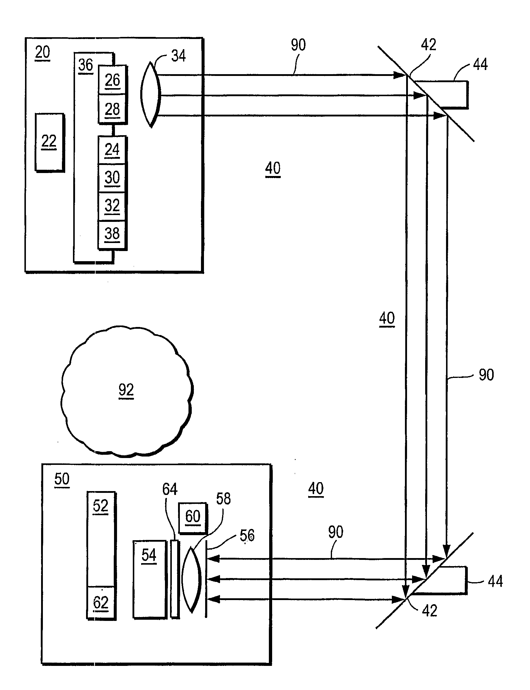
[0040]As shown in the examples of FIGS. 2 and 3, one embodiment of the wireless power beaming system includes a transmitter assembly 20, a free space optical path 40, and an optical-to-electric power converter 50 for the device being powered. Transmitter assembly 20 converts electricity to light 90. The light 90 travels through free space 40 to an optical-to-electric power converter 50.

[0041]In one embodiment, the transmitter assembly 20 can include a high-efficiency, eye-safe, light source 26 to transmit power; lens(es) 34 and pointing mechanism 36 for focusing and aiming the lasers; and a CPU 22. For example, a laser light source 26 can operate at wavelengths greater than 1400 nm. Examples of such lasers are made by nLight Photonics, Inc, Princeton Lightwave, Covega, and other manufacturers. Light 90 from the laser(s) 26 passes through lens(es) 34 for focusing and aiming the lasers. In a preferred embodiment, the outgoing light 90 is nearly collimated, has a substantially uniform ...


PUM

PropertyMeasurementUnit
wavelengthaaaaaaaaaa
wavelengthsaaaaaaaaaa
poweraaaaaaaaaa

Abstract

In one embodiment, a transmitter assembly containing a light source is electrically powered. The light source receives electrical power and converts the electrical power to an optical power beam that is directed through free space to an optical-to-elect power converter for a device. The optical-to-electric power converter converts the optical power beam to electrical form, thus providing electrical power to a device. A safety subsystem assures that the emission beyond the hot zone between the transmitter and receiver do not exceed regulatory levels.

Description

RELATED APPLICATIONS[0001]This application claims priority from the U.S. provisional patent application Ser. No. 60 / 866,807 entitled “Reflection-Safe Receiver for Power Beaming”, filed Nov. 21, 2006, the disclosure of which is incorporated herein by this reference.BACKGROUND OF THE INVENTION[0002]1. Field of the Invention[0003]This invention relates to free space optical transmission of power to electrically-powered devices.[0004]2. Description of the Related Art[0005]Common home and business electrical and electronic devices typically receive power from five types of sources: (1) wall outlets, (2) other electrical devices, (3) rechargeable batteries, (4) disposable batteries, and (5) solar cells.[0006]First, many common home and business electrical and electronic devices are plugged into wall outlets. An example is a lamp with a power cord. The length of the cord limits how far away the lamp can be placed from the outlet. The cord can get tangled or become a trip hazard. The cord m...

Claims


Application Information

Patent Timeline
Patent Type & Authority Applications(United States)
IPC IPC(8): G01D5/30H01L31/04G01N21/47
CPCH02J5/00H04B10/807H02J17/00H02J50/30
Inventor GRAHAM, DAVID S.
Owner GRAHAM DAVID S
Why Eureka
Try Eureka