
Feedback circuit for line load compensation and reflection reduction

a feedback circuit and line load technology, applied in the direction of instruments, computation using denominational number representation, pulse technique, etc., can solve the problems of star topology having the added cost of a hub, failure of the entire network, and difficulty in troubleshooting network issues, etc., to achieve the effect of reducing reflection

Inactive Publication Date: 2007-07-19
HONEYWELL INT INC
View PDF5 Cites 108 Cited by
  • Summary
  • Abstract
  • Description
  • Claims
  • Application Information

AI Technical Summary

Benefits of technology

[0014] A further object of the present invention is to provide reduced reflection within the signal lines caused by un-terminated lines and devices.

Problems solved by technology

However, a break in the main cable results in the failure of the entire network.
Generally, troubleshooting network issues can be difficult especially if the problem causes the entire network to fail.
However, star topology has the added cost of a hub over the linear bus and while generally reliable, if the hub fails, all nodes attached to the hub are disabled.
Due to the Ethernet protocol requirement that a signal transmitted on the network cable must reach every part of the network within a specified length of time, the tree topology is limited in the number of hubs it can implement.
However, by its very nature, free-topology is subject to variable line, i.e., network cable, loads as well as signal reflection caused by unterminated lines.
In this post-construction case, it is difficult and costly to run wiring needlessly.
Security monitoring systems that are tied to one topology or another are less desirable, in that such a system may be perfectly suited for one installation scenario, and woefully ill-suited for the multiple other installation scenarios that may be encountered.

Method used


Image

  • Feedback circuit for line load compensation and reflection reduction
  • Feedback circuit for line load compensation and reflection reduction
  • Feedback circuit for line load compensation and reflection reduction

Examples


Embodiment Construction

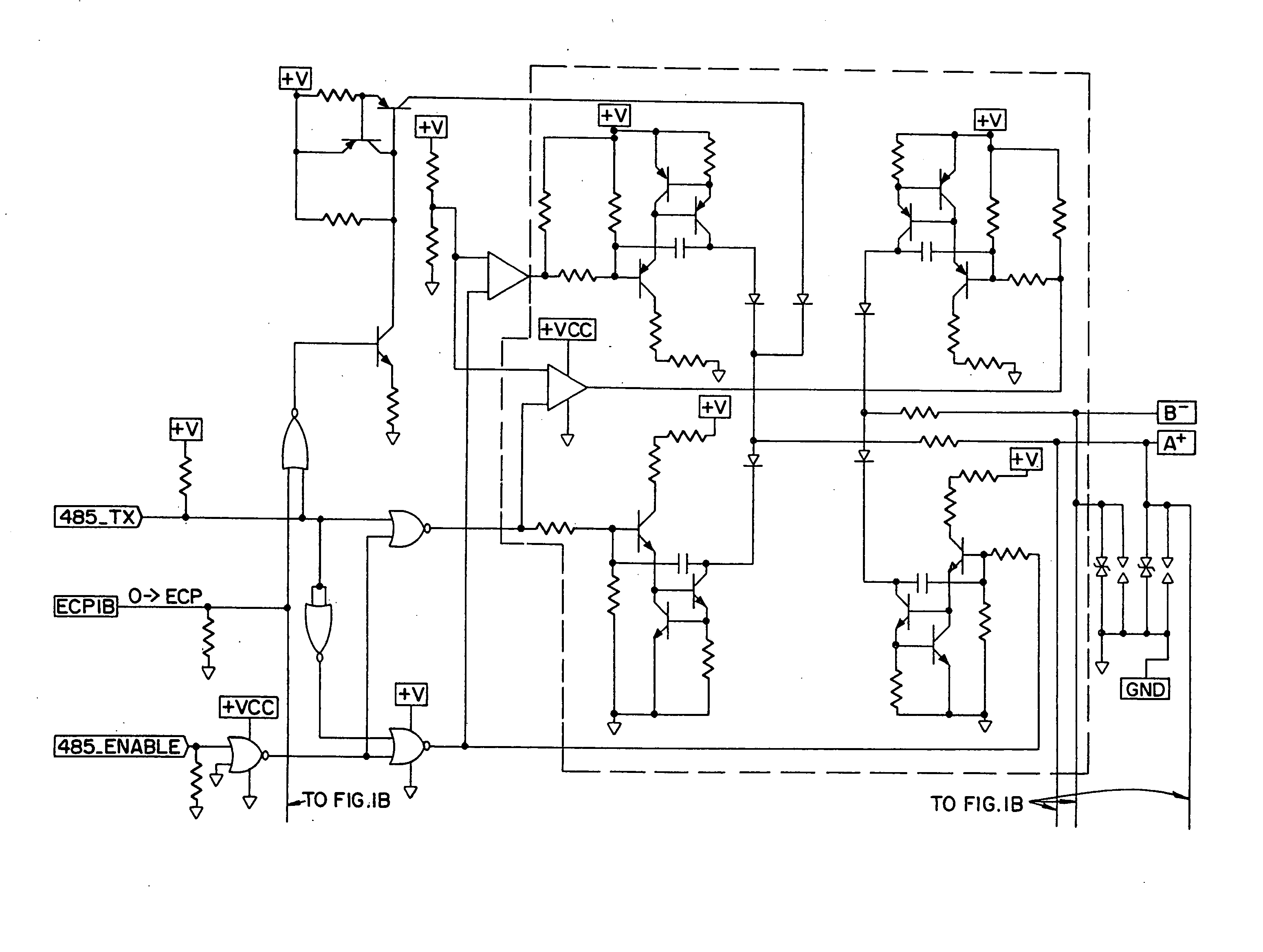
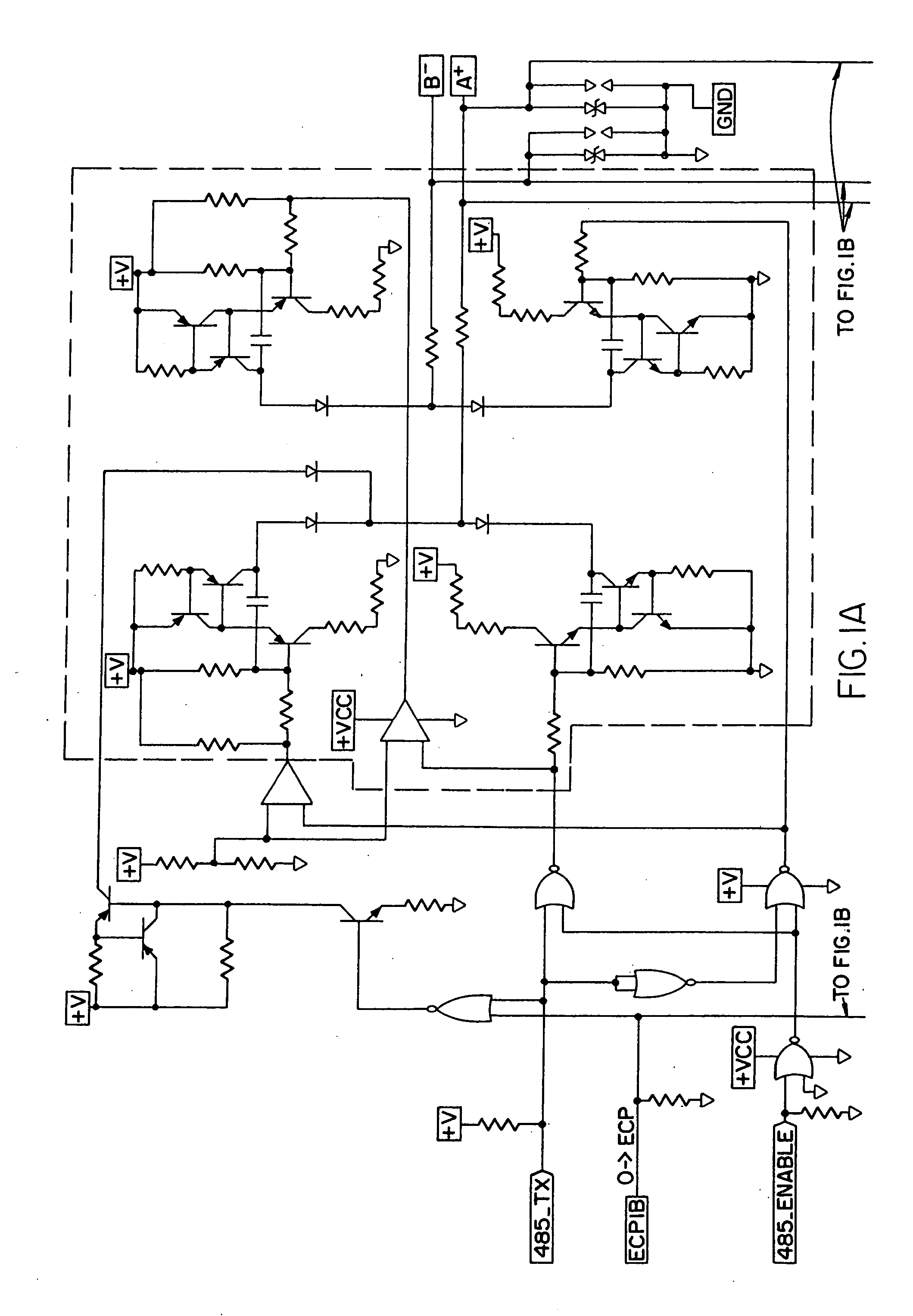
[0022] Differential drive circuits, such as the IB 485 driver, require a free typology, thus the line load is variable. However, allowing a variable load on a signal line may result in signal reflection due to unmatched impedances. To produce an output that is independent of the load, the present invention integrates feedback capacitors into the differential drive circuitry.

[0023] The feedback capacitors are selected so that the resulting rise / fall time is the slowest practical rise / fall time for a particular baud rate. Preferably, the slowest rise / fall time is ⅓ of the maximum bit transmission time, determined by the desired baud rate and maximum transmission line length. The rise / fall time is defined as the product of the capacitance and resistor time constant of the circuit. Therefore, the preferred rise / fall time is set by selecting the appropriate capacitance value of the feedback capacitor and / or adjusting the resistance of the feedback circuit.

[0024] The current through the...


PUM


Abstract

Line load compensation and reflection reduction in a signal transmitting circuit is provided using feedback capacitors. The feedback capacitor serially coupled with a resistance generates an RC rise / fall time that is independent of the line load. Additionally, by selecting a capacitor that yields a rise / fall time of approximately ⅓ of the maximum bit transmission time, signal reflection on the signal line can be reduced. Accordingly, by incorporating the feedback capacitor with a differential drive circuit, such as the IB 485 driver, variations in line load can be compensated for while also reducing signal reflection due to un-terminated or improperly terminated signal lines, thus allowing a free topology implementation.

Description

I. BACKGROUND OF THE INVENTION [0001] The present invention relates generally to electrical circuit device drivers. More specifically, the present invention is directed to a feedback circuit for line load compensation and reflection reduction in free-topology module wiring configurations. [0002] Computer systems and control systems connect to peripherals, sensors, and other electronic devices by means of various connection methods. Wired devices can be connected in various configurations, or topologies, such as linear bus, tree, star and star-wired ring configuration. The topology used is generally dependent on the particular communication protocol being implemented. For example, Token Ring utilizes a star-wired ring topology, while RS-485 requires a linear bus typology. Each topology has benefits and disadvantages. [0003] A linear bus topology consists of a main run of cable onto which, devices, or nodes, are patched. Linear bus topology is easy to connect and may be more economica...

Claims


Application Information

Patent Timeline
Patent Type & Authority Applications(United States)
IPC IPC(8): H03K17/16
CPCH04L25/0298H04L25/0272
Inventor WESTON, LANCEHINKSON, RICHARD H.MOLE, DAVID
Owner HONEYWELL INT INC
Learn More