Blade mounting structure of bulldozer

a technology of mounting structure and bulldozer, which is applied in the direction of construction, agricultural machines, agricultural tools and machines, etc., can solve the problems of increased entire weight of the blade, difficult to secure, and insufficient workability, so as to improve the weight balance of the entire bulldozer, enhance the driving performance of the blade, and enhance the traveling performance

Inactive Publication Date: 2006-03-21
KOMATSU LTD
View PDF29 Cites 23 Cited by
  • Summary
  • Abstract
  • Description
  • Claims
  • Application Information

AI Technical Summary

Benefits of technology

[0006]The present invention is made in view of the above-described problems, and has its object to provide a blade mounting structure of a bulldozer capable of increasing visibility of a blade and reducing entire weight of the blade and manufacturing cost.
[0008]According to the above constitution, only any one of the set of left and right straight frames and the substantially central portion of the blade are connected with the arm to be swingable up and down and to the left and the right, and the load in the left and right direction exerted on the blade is supported by only the arm at the one side, whereby the attitude of the blade can be held. Further, this structure makes it possible to tilt-drive the blade following the extension and contraction of the hydraulic cylinder for tilt drive. Consequently, the link member is not needed between the blade and the arm, and the blade position is located near to the vehicle body by the space for the link member, thus making it possible to enhance the driving performance of the blade, and improving the weight balance of the entire bulldozer to make it possible to enhance traveling performance. In addition, the distance between the blade and the vehicle body is shortened, and therefore visibility of the blade becomes favorable.
[0009]Since the blade is provided to be close to the arm, the area in which visibility of the blade is hindered by the arm is reduced, and visibility of the blade can be increased. Further, since the arm is provided at only any one of the left and the right sides, visibility of the blade end portion opposite to the arm mounted side can be increased, and blade operability can be enhanced. Since the number of the arm is only one, the number of welded spots of the arm connecting member is reduced, and the rigidity distribution of the blade can be concentrated on the arm mounted side. Consequently, the weight of the entire blade can be reduced, the manufacturing cost can be reduced and the grease supplying operation for the connecting portions can be facilitated.
[0010]In the blade mounting structure of a bulldozer: a connection point of the arm and the blade may be provided at an upper portion from a line connecting connection points of the set of left and right straight frames and the blade. According to this constitution, the left and right tilt amounts of the blade can be equalized, and therefore operability of the blade at the time of tilt can be enhanced, thus making it possible to enlarge the application range of this bulldozer. There is no fear that the arm interferes with the ground, rocks and stones, or the like during operation of the blade, and therefore favorable operability of the blade is provided.
[0011]In the blade mounting structure of a bulldozer: length of the arm may be variable. According to this constitution, the arm length is made variable, and therefore it becomes possible to off-set the blade to the left and the right with respect to the center of the vehicle body in the longitudinal direction, and to use the bulldozer as an angledozer by inclining the blade to the left and right direction, thus making it possible to enlarge the application range of this bulldozer.

Problems solved by technology

However, in the above-described conventional blade mounting structure, the following problems exist.
Consequently, it becomes difficult to secure visibility of the blade 1 from a driver's cab 7 provided at the vehicle body (especially, the visibility of a left portion of the blade from the driver's cab 7 which is normally provided to be set aside on a left side of the vehicle body), and there arises the problem that favorable workability is not provided at the time of a ground leveling operation and the like by the blade 1.
Since the number of arms 2, 2, 2a and 2a is large, the number of welded spots of the ball joints and the like which are their connecting members is large, thus causing the problem that the entire weight of the blade is increased by welding for securing the base material strength and the welding operation time is required to increase the manufacturing cost.
Further, there are many spots to be supplied with grease such as ball joints, and therefore there exists the problem of reduction in maintainability.

Method used


Image

  • Blade mounting structure of bulldozer
  • Blade mounting structure of bulldozer
  • Blade mounting structure of bulldozer

Examples


Embodiment Construction

[0021]A preferred embodiment of the present invention will be explained in detail below with reference to the drawings.

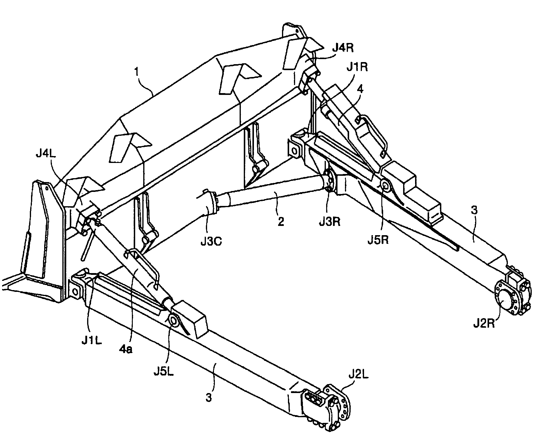
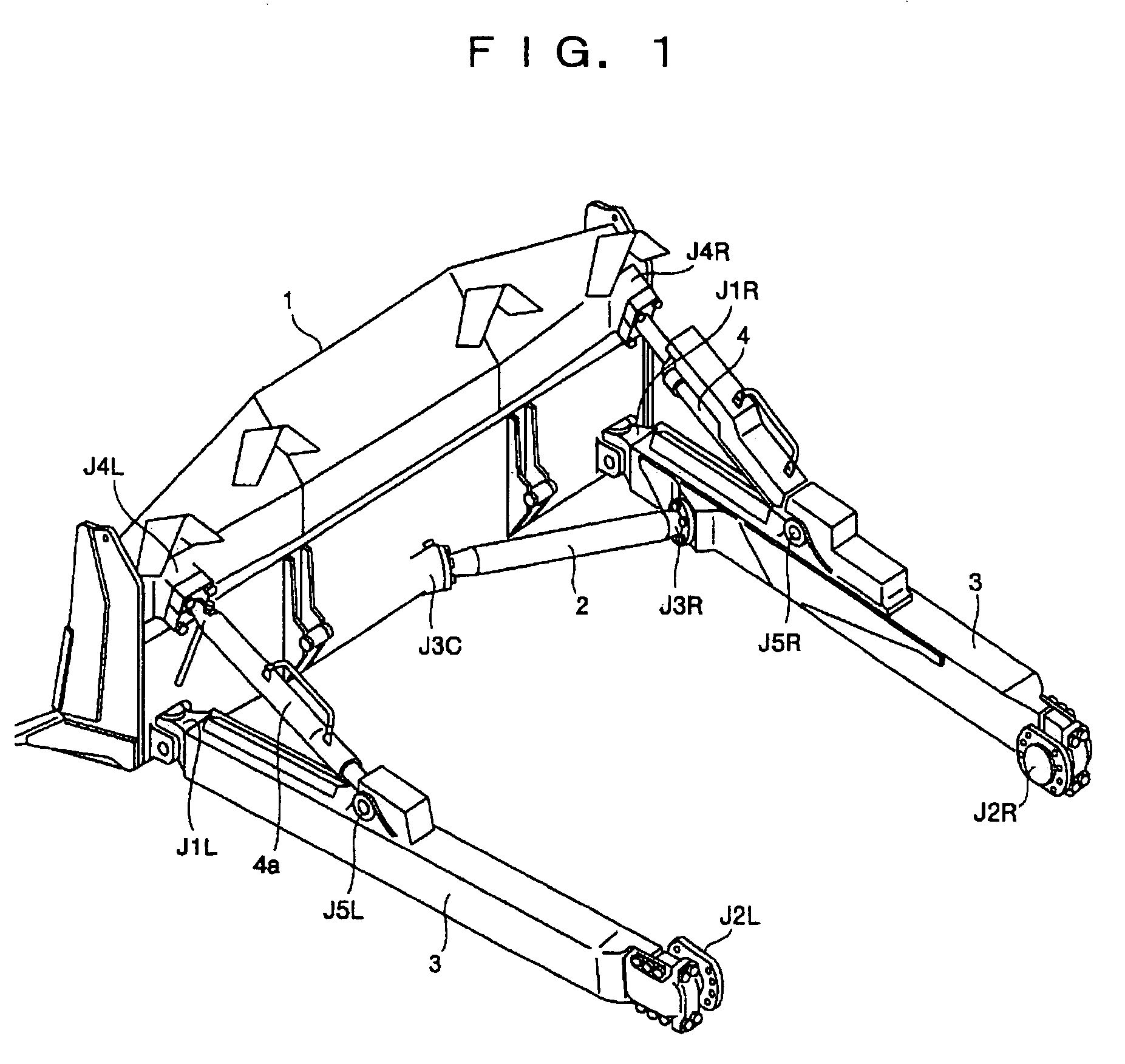
[0022]FIG. 1 is a perspective view of a mounting structure of a blade according to the embodiment. In the below, components having substantially the same functions as the components shown in FIG. 8 are given the same reference numerals and symbols and explanation thereof will be omitted. An arm 2 is connected to a substantially central lower portion of the blade 1 and a straight frame 3 via ball joints J3C and J3R at only either one of left or right side. When a driver's cab 7 (see FIG. 9) is provided on a left side of a vehicle body, it is preferable to provide the one arm 2 at a right side of the blade 1 to enhance visibility from the driver's cab 7. Rigidity of the blade 1 against an external force in a left and right direction is secured by the one arm 2. The ball joint J3R may be a pin joint.

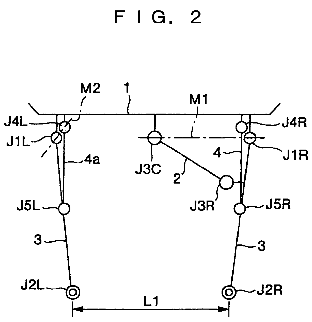
[0023]Next, based on FIG. 2 to FIG. 4, an operation of the blade with ...


PUM


Abstract

A blade mounting structure of a bulldozer capable of increasing visibility of a blade is provided. For this purpose, in the blade mounting structure in which a left and a right portions of a blade (1) and a vehicle main body are connected with a set of left and right straight frames (3, 3) to be swingable up and down and to a left and a right, and the straight frames and the blade are respectively connected by a hydraulic cylinder (4) for tilt drive and a support member (4a) to be swingable up and down and to the left and the right to be constituted to be capable of tilt drive, the blade mounting structure includes an arm (2) for connecting only any one of the straight frames and a substantially central portion of the blade to be swingable up and down and to the left and the right.

Description

TECHNICAL FIELD[0001]The present invention relates to a blade mounting structure of a bulldozer which is capable of tilt.BACKGROUND ART[0002]In a blade of a bulldozer, a structure as shown in, for example, FIG. 8 is conventionally known as a blade mounting structure for inclining (hereinafter, called tilt) the blade in a left and right direction. In FIG. 8, tip end portions of a set of left and right straight frames 3 and 3 are connected to lower portions of left and right end portions of a blade 1 via connecting members J1L and J1R such as ball joints or cross joints (joints each having a pin turning in an up-and-down direction and a pin turning in a left and right direction) to be swingable up and down and to a left and a right. Base end portions of the set of left and right straight frames 3 and 3 are connected to left and right portions of a set of left and right traveling unit frames 6 at a side of a bulldozer vehicle body via ball joints J2L and J2R respectively to be swingabl...

Claims


Application Information

Patent Timeline
Patent Type & Authority Patents(United States)
IPC IPC(8): E02F3/76
CPCE02F3/7618E02F3/7613
Inventor MATSUMOTO, NORIHISAWADA, TATSUO
Owner KOMATSU LTD
Why Eureka
Try Eureka