

Anti-drawback medical valve
- Summary
- Abstract
- Description
- Claims
- Application Information
AI Technical Summary
Benefits of technology
Problems solved by technology
Method used
Image

Examples
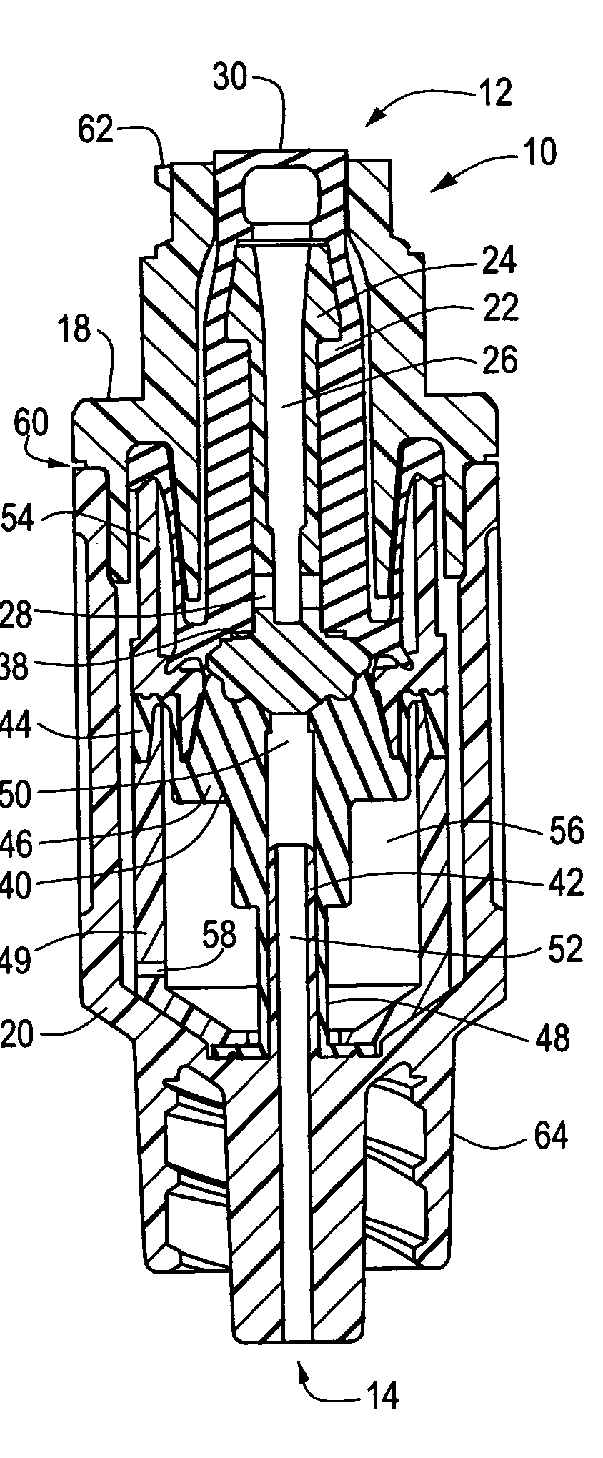
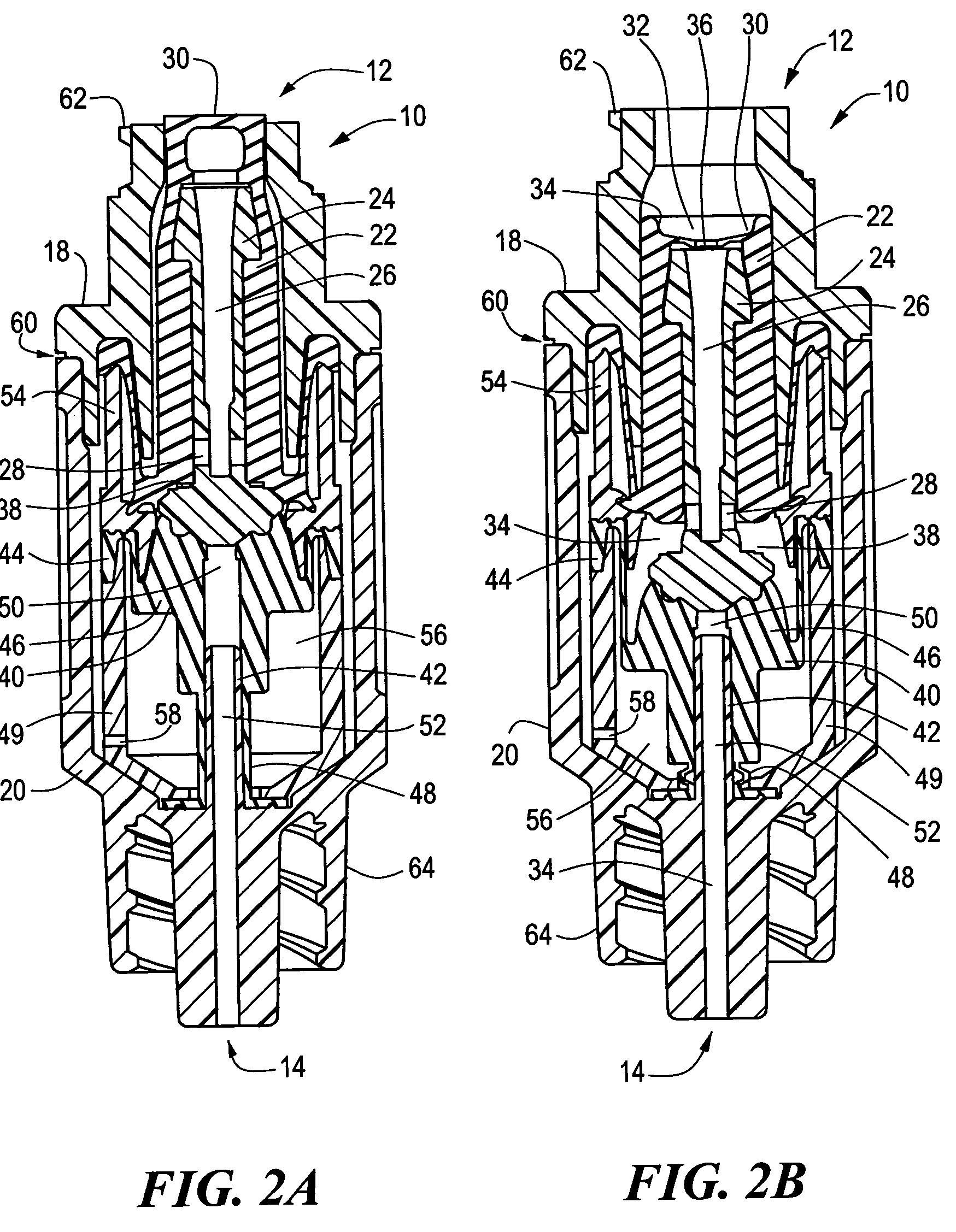
first embodiment
[0044]Unlike the first embodiment shown in FIGS. 2A and 2B, the outlet housing portion 20A of this embodiment includes a first portion 66 and a second portion 68. The first portion 66 secures directly to the inlet housing portion 18 to secure the gland 22A within the valve 10, while the second portion 68 secures to the distal end of the first portion 66 to lock a mechanically collapsible element (“collapsible element 70”) within the valve 10.
[0045]The collapsible element 70 collapses as the cannula 24A is urged distally. When the collapsible element 70 is collapsed, the variable volume region 38A has a volume that is greater than when the collapsible element 70 is not collapsed. Among other things, the collapsible element 70 includes a bellows 72. The collapsible element 70 also includes a securing ring 74 that acts as a spring. Specifically, the securing ring 74 normally applies a proximally directed force to the remainder of the collapsible element, thus normally biasing such elem...
second embodiment
[0048]Various dimensions for the elements of this second embodiment may be as follows:[0049]Maximum outer diameter of inlet housing: 0.46 inches;[0050]Length of second portion of outlet housing: 0.68 inches;[0051]Total length of valve 10: 1.37 inches; and[0052]Width of distal port 14: 0.08 inches.
[0053]Although these dimensions are discussed as potential dimensions, they are not intended to limit the scope of the invention. Nevertheless, these dimensions are useful in estimating fluid volume within the variable volume region 38A. It has been determined, on paper, that when closed (FIG. 3A), a valve 10 with these dimensions should have an interior volume (for containing fluid) of about 0.144 cubic centimeters. This interior volume includes the variable volume region 38A and the outlet path located distally of the collapsible member 56. When open (FIG. 3B), it has been determined, on paper, that a valve 10 with these dimensions should have an interior volume (for containing fluid) of ...
PUM
 Abstract
Description
Claims
Application Information