
Decorative lighting device

Inactive Publication Date: 2006-03-21
HARRISON BARBARA +1
View PDF8 Cites 2 Cited by
  • Summary
  • Abstract
  • Description
  • Claims
  • Application Information

AI Technical Summary

Benefits of technology

[0006]Accordingly, it is an object of the present invention to provide an improved decorative lighting device.
[0008]An additional object of the present invention is to provide an improved decorative lighting device which can provide a multiplicity of decorative and esthetically pleasing patterns.

Problems solved by technology

However, there is a constant search for new and different devices and none of the prior art devices have been entirely satisfactory.

Method used


Image

  • Decorative lighting device
  • Decorative lighting device
  • Decorative lighting device

Examples


Embodiment Construction

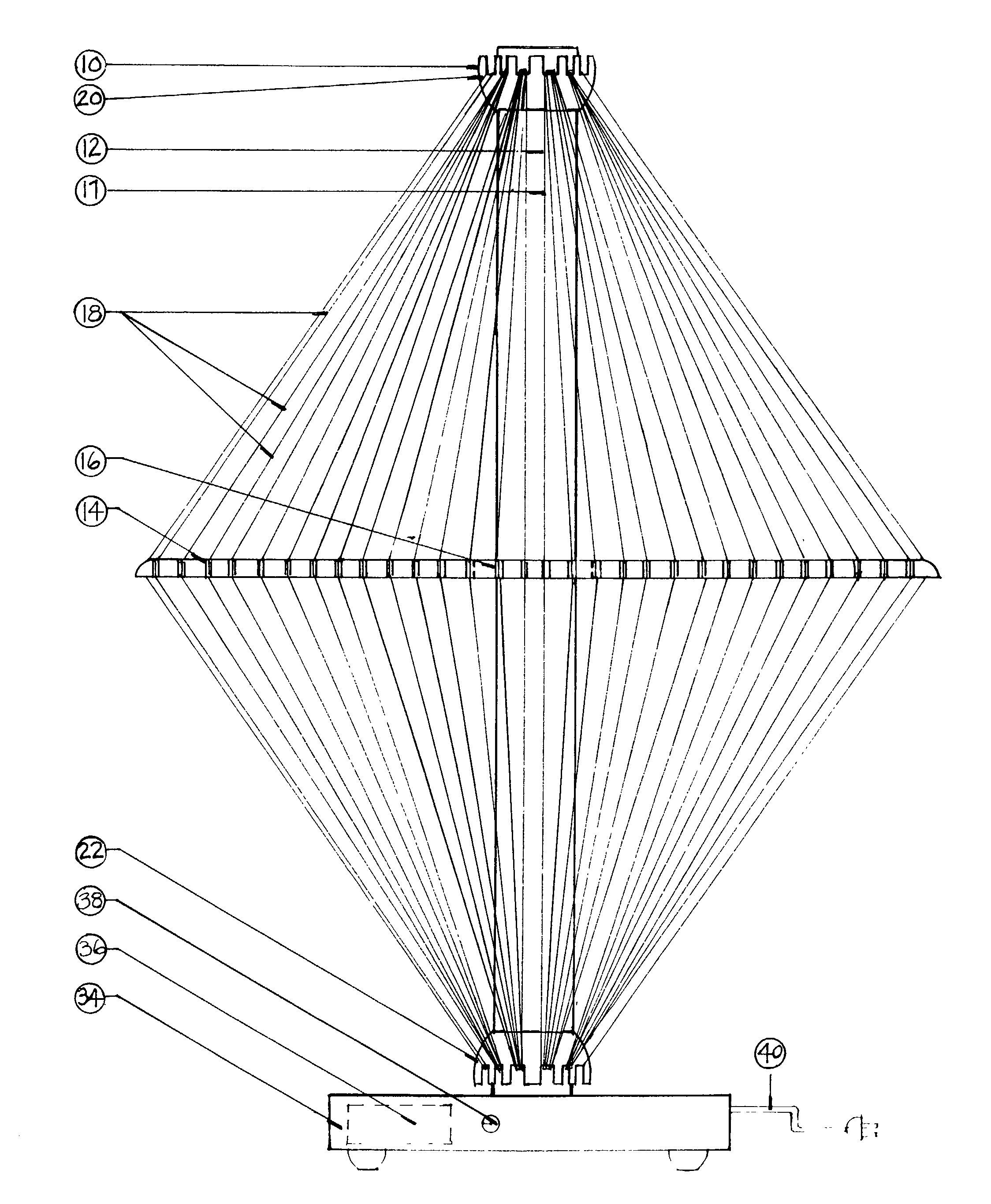
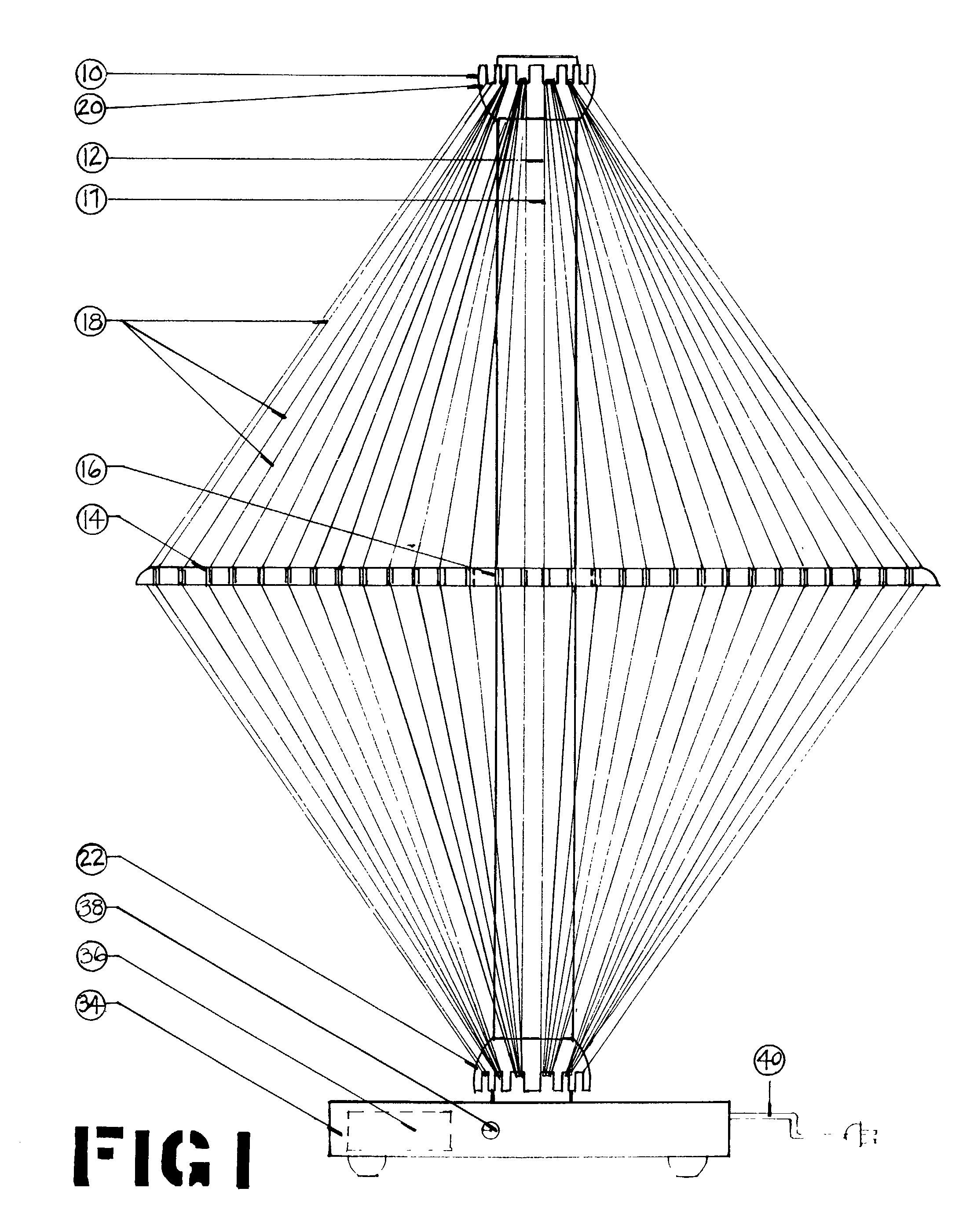
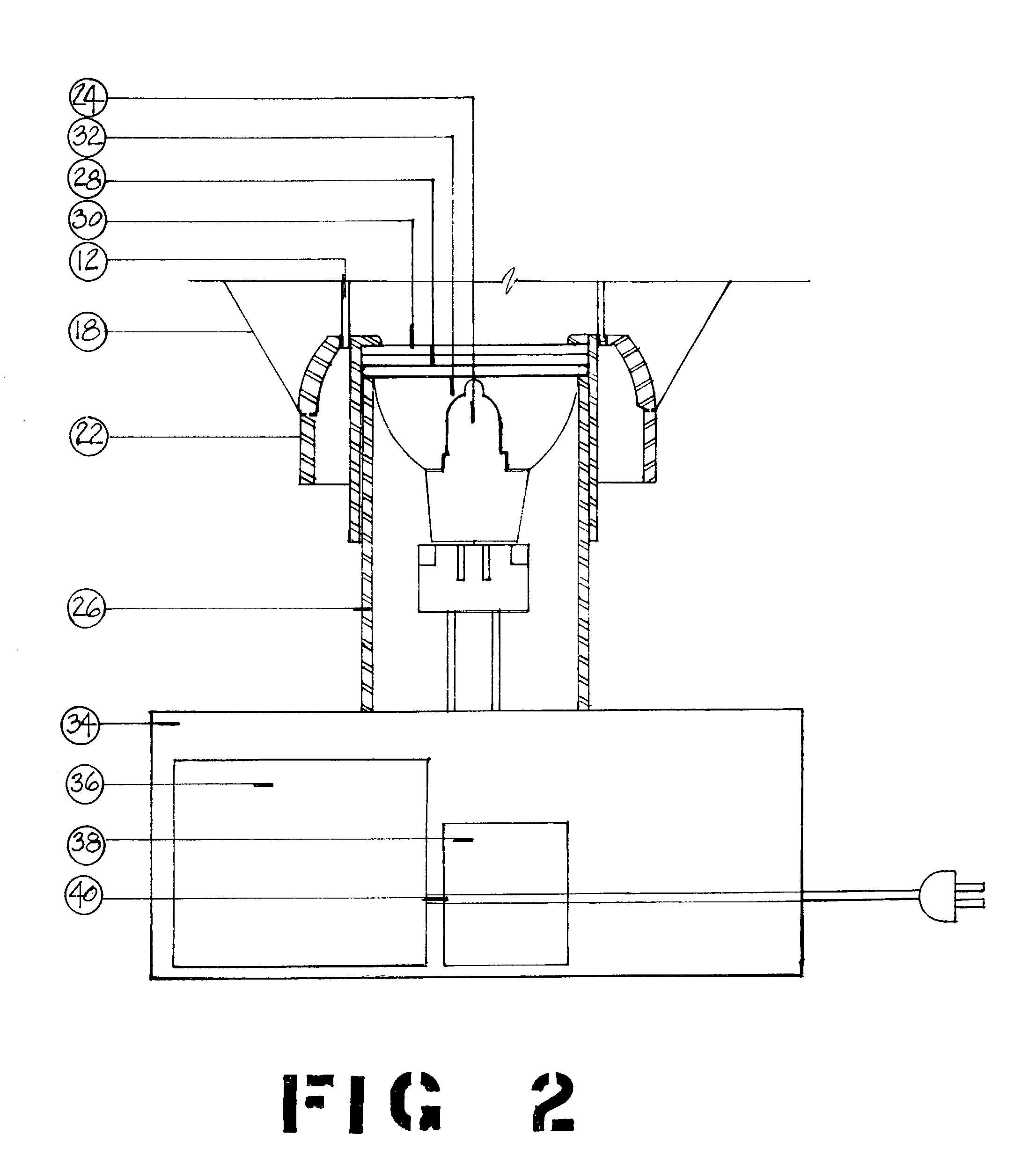
[0016]In that form of the present invention chosen for purposes of illustration, FIG. 1 shows a decorative lighting device, indicated generally at 10, having a central column 12. The column 12 is preferably formed of thin material, of less than about 1 / 16th inch thickness and preferably about 22 guage, and may be formed of metal or other self-supporting material. As seen in FIG. 1, the column 12 is circular in cross section and may be opaque or translucent and is perforated as seen at 17, preferably in a lincane pattern. This allows light to pass through the perforations, yet prevents undesired banding shadows. However, it should be clearly understood that the central column 12 is hollow and may have substantially any desired cross section. Thus, for example, as seen in FIG. 4, the central column 12 is rectangular in cross section. The column 12 may be used alone. Preferably, however, at least one rigid member 14 is located about the column 12 and lies in a plane substantially perpe...


PUM


Abstract

An improved decorative lighting device comprising a central column containing at least one light source, a rigid member lying in a plane substantially perpendicular to the axis of said column, and a plurality of optical fibers extending from a point adjacent the top of said column about said rigid member to a point adjacent the bottom of said column.

Description

RELATED CASES[0001]This invention is described in my Provisional Patent Application, Ser. No. 60 / 358,802, filed May 2, 2002, and now abandoned.FIELD OF INVENTION[0002]This invention relates to electrical lighting and is particularly directed to improved lighting devices for providing decorative and attractive patterns.PRIOR ART[0003]The world is constantly seeking new and different devices which are esthetically pleasing and which provide calming, relaxing and meditatively stimulating experiences. Over the years, numerous such devices have been popular for some period of time and which have subsequently been replaced by newer such devices. Lava lights, fiber optic spray lamps, etc. are examples of such decorative lights. However, there is a constant search for new and different devices and none of the prior art devices have been entirely satisfactory.BRIEF SUMMARY AND OBJECTS OF INVENTION[0004]These disadvantages of the prior art are overcome with the present invention and an improv...

Claims


Application Information

Patent Timeline
IPC IPC(8): A47G35/00G02B6/00
CPCG02B6/0008G02B6/0006F21S10/005Y10S362/806
Inventor HARRISON, BARBARAHARRISON, JR., ORLAND L.
Owner HARRISON BARBARA
Learn More