Omnidirectional eddy current probe and inspection system

a technology of eddy current probe and inspection system, which is applied in the direction of magnetic property measurement, material magnetic variables, instruments, etc., can solve the problems of laborious and time-consuming process, limited utility of the eddy current probe described above,

Inactive Publication Date: 2006-03-21
GENERAL ELECTRIC CO
View PDF26 Cites 126 Cited by
  • Summary
  • Abstract
  • Description
  • Claims
  • Application Information

AI Technical Summary

Problems solved by technology

However, the eddy current probes described above are limited in their utility by the fact that a prior knowledge of crack orientation is required.
The repeated scanning makes this process laborious and time consuming.

Method used


Image

  • Omnidirectional eddy current probe and inspection system
  • Omnidirectional eddy current probe and inspection system
  • Omnidirectional eddy current probe and inspection system

Examples


Embodiment Construction

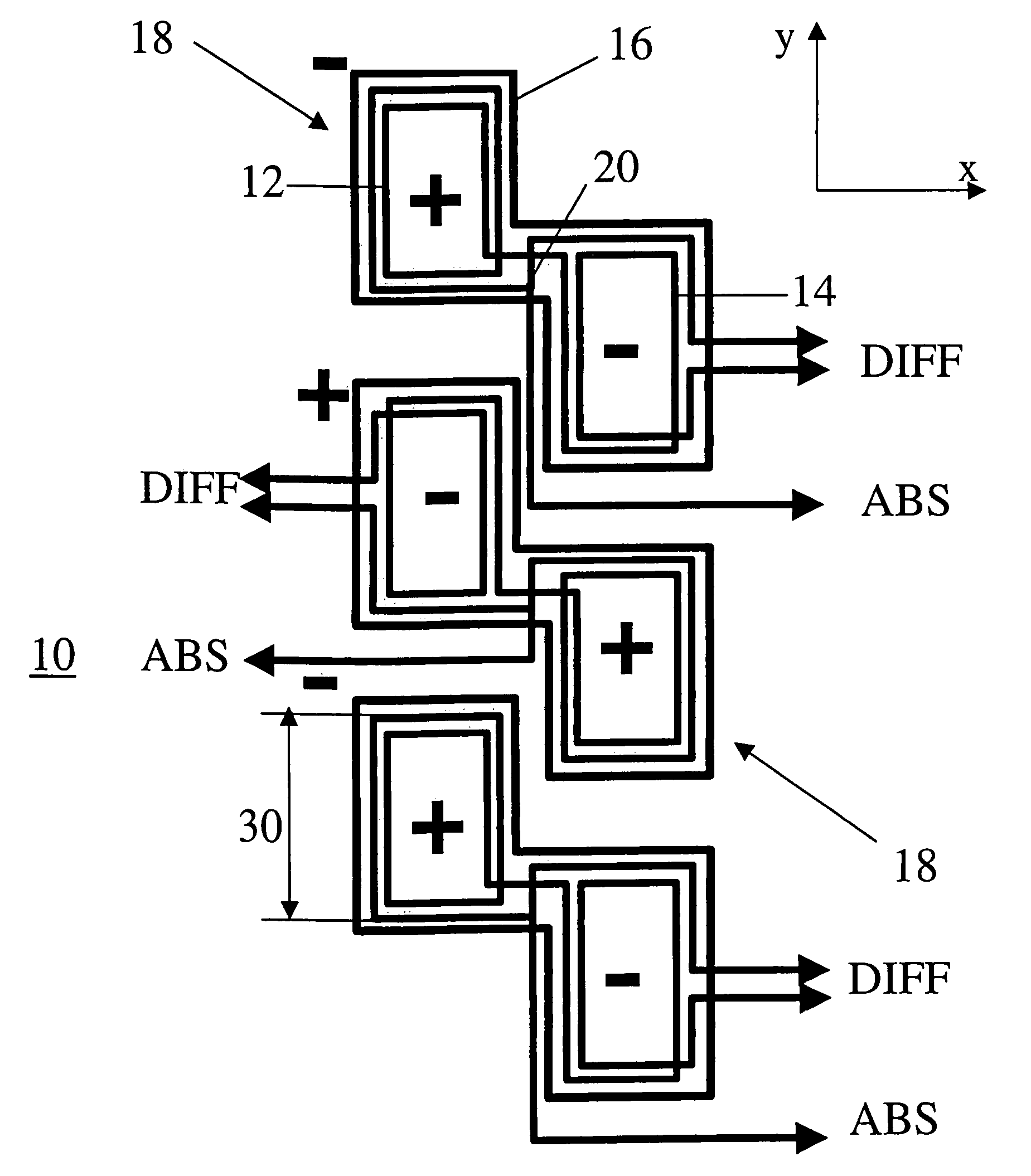
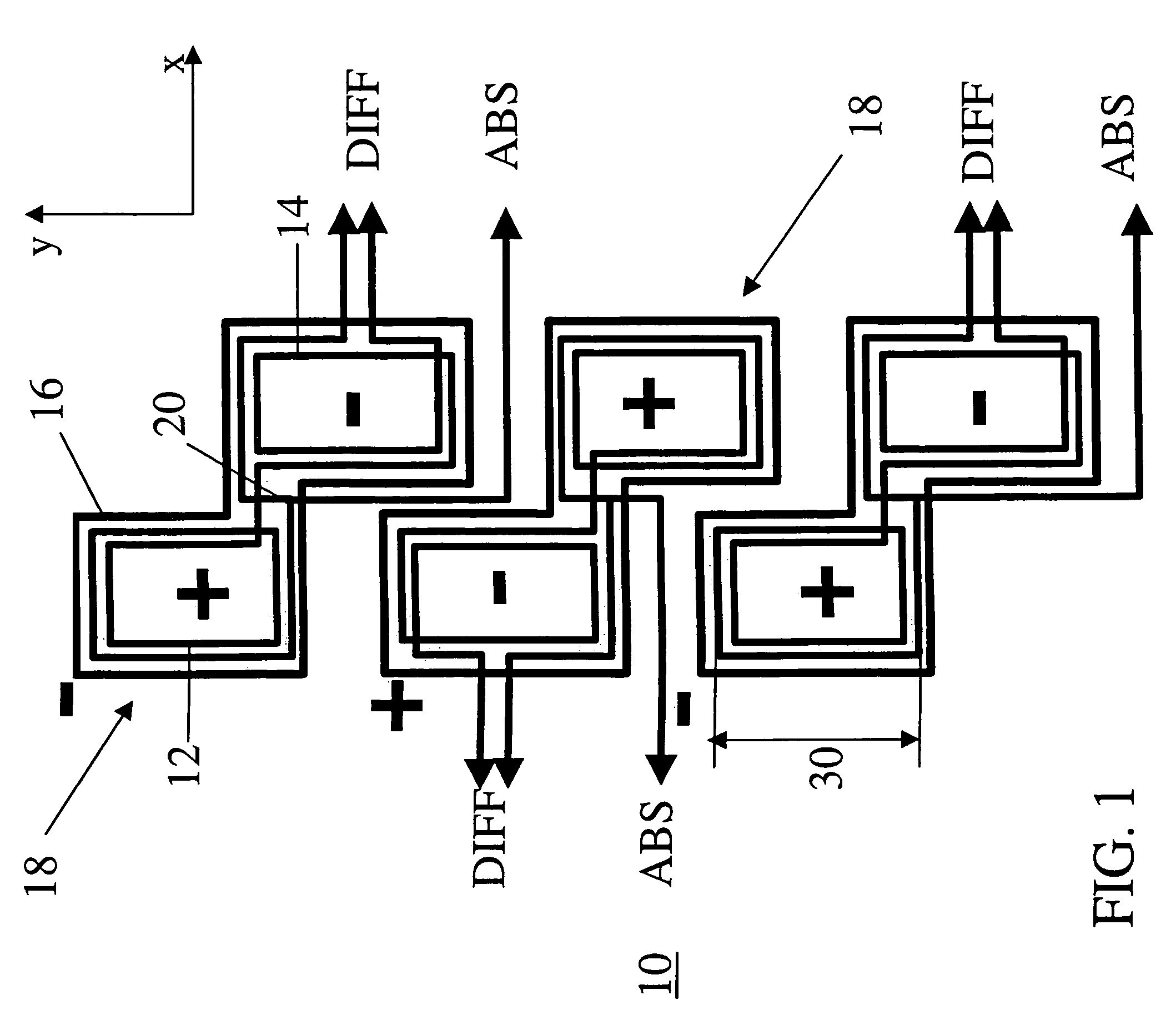
[0015]FIG. 1 illustrates an omnidirectional eddy current (EC) probe 10 embodiment of the invention. As shown in FIG. 1, the omnidirectional EC probe 10 includes at least one eddy current (EC) channel 18. The EC channel 18 includes a first sense coil 12 and a second sense coil 14. As shown, first and second sense coils 12, 14 are offset from one another in a first (x) and a second (y) direction and overlap one another in at least one of the first and second directions (x,y). As used herein, the terms “offset” and “overlap” are not mutually exclusive. For example, the exemplary first and second sense coils 12, 14 in FIG. 1 are both offset and overlap in the y direction. In other words, for this configuration, the first and second sense coils 12, 14 are partially offset in the y direction, whereas they are completely offset (no overlap) in the x direction. According to a specific embodiment, the first and second sense coils 12, 14 overlap in the second direction y by at least about twe...


PUM

PropertyMeasurementUnit
lengthaaaaaaaaaa
thickaaaaaaaaaa
thickaaaaaaaaaa

Abstract

An omnidirectional eddy current (EC) probe includes at least one EC channel having a first and a second sense coil that are offset in a first (x) and a second (y) direction and overlap in at least one of the directions (x,y). At least one drive coil is configured to generate a probing field for the EC channel in a vicinity of the sense coils. An omnidirectional EC inspection system includes an omnidirectional EC array probe (ECAP) that includes a number of EC channels and drive coils. Each EC channel includes first and second sense coils with opposite polarities. The drive coils have alternating polarities. Electrical connections perform differential sensing for respective EC channels. Corrective drive coils are disposed at respective ends of the EC channels and generate probing fields. An eddy current instrument is connected to the omnidirectional ECAP and receives differential sensing signals from the EC channels.

Description

BACKGROUND OF THE INVENTION[0001]The present invention relates generally to eddy current inspection and, more specifically, to eddy current probes for non-destructive testing of conductive materials.[0002]Eddy current inspection is a commonly used technique for non-destructive testing of conductive materials for surface flaws. Eddy current inspection is based on the principle of electromagnetic induction, wherein a drive coil carrying currents induces eddy currents within a test specimen, by virtue of generating a primary magnetic field. The eddy currents so induced in turn generate a secondary magnetic field, which induces a potential difference in the sense coils, thereby generating signals, which may be further analyzed for flaw detection. In the case of a flaw in the test specimen, as for example, a crack or a discontinuity, the eddy current flow within the test specimen alters, thereby altering the signals induced in the sense coils. This deviation in the signals is used to ind...

Claims


Application Information

Patent Timeline
Patent Type & Authority Patents(United States)
IPC IPC(8): G01N27/90G01N27/72G01D5/20G01R33/02G01R33/12
CPCG01N27/904G01N27/902G01N27/9006
Inventor WANG, CHANGTINGPLOTNIKOV, YURI ALEXEYEVICHNATH, SHRIDHAR CHAMPAKNATHMCKNIGHT, WILLIAM STEWARTGAMBRELL, GIGI OLIVE
Owner GENERAL ELECTRIC CO
Why Eureka
Try Eureka