Image processing method for direction dependent low pass filtering

a processing method and low-pass filtering technology, applied in the field of image processing methods, can solve the problem of losing the original high-definition structure of image data

Inactive Publication Date: 2006-03-21
NIKON CORP
View PDF7 Cites 114 Cited by
  • Summary
  • Abstract
  • Description
  • Claims
  • Application Information

AI Technical Summary

Benefits of technology

[0005]An object of the present invention is to provide an image processing technology that enables l...

Problems solved by technology

However, while a noise removal effect is achieved through normal isotopic filtering processing, i.e., through filtering pr...

Method used


Image

  • Image processing method for direction dependent low pass filtering
  • Image processing method for direction dependent low pass filtering
  • Image processing method for direction dependent low pass filtering

Examples


first embodiment

[0075]The image processing method in the first embodiment is implemented by executing an image processing program on a computer. If the image processing program is recorded in a recording medium such as a CD-ROM, the image processing program is copied onto a hard disk at the computer from the recording medium set at the computer for use. Alternatively, the image processing program may be downloaded onto the hard disk at the computer via a communication network such as the Internet for use.

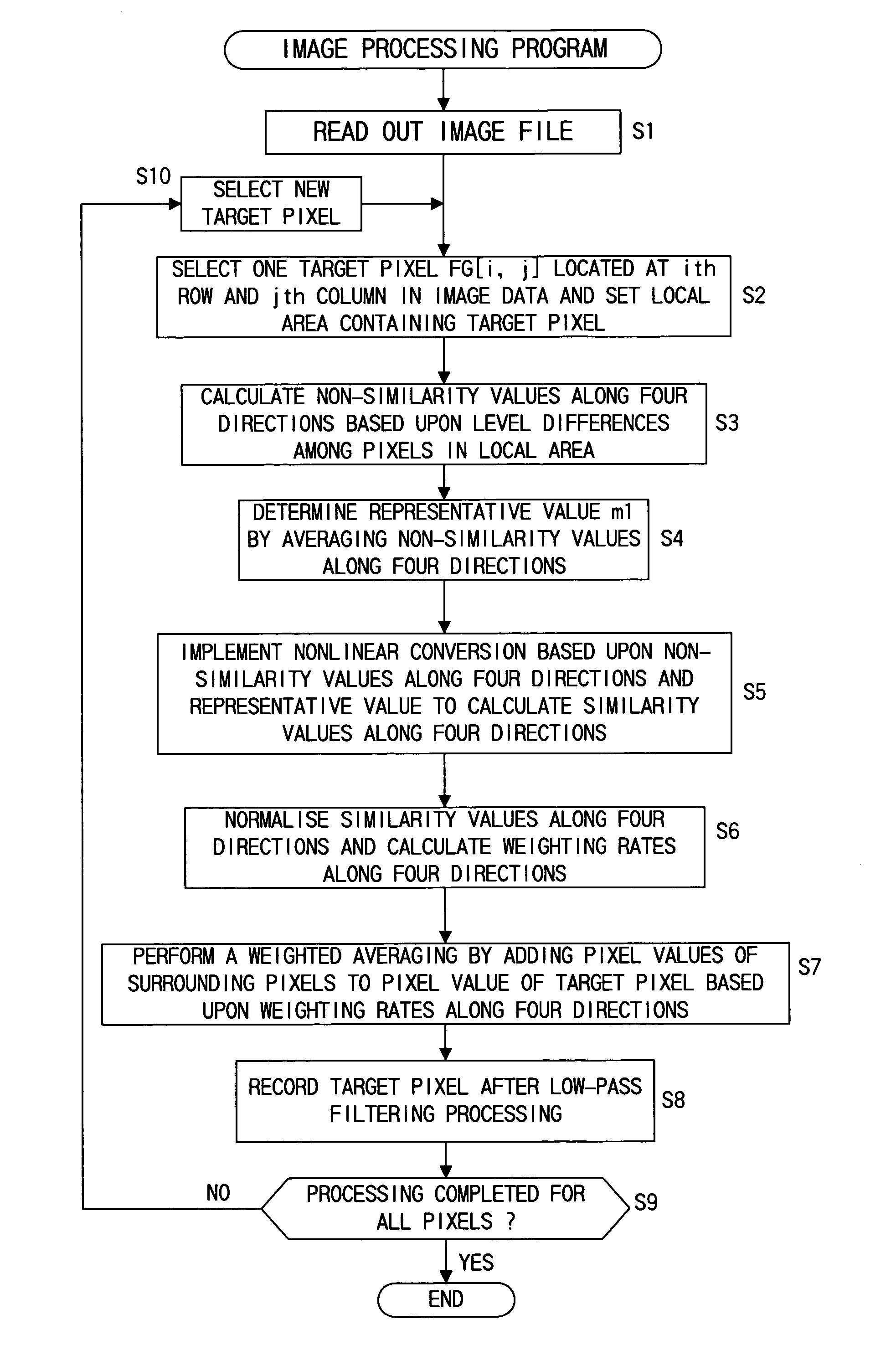
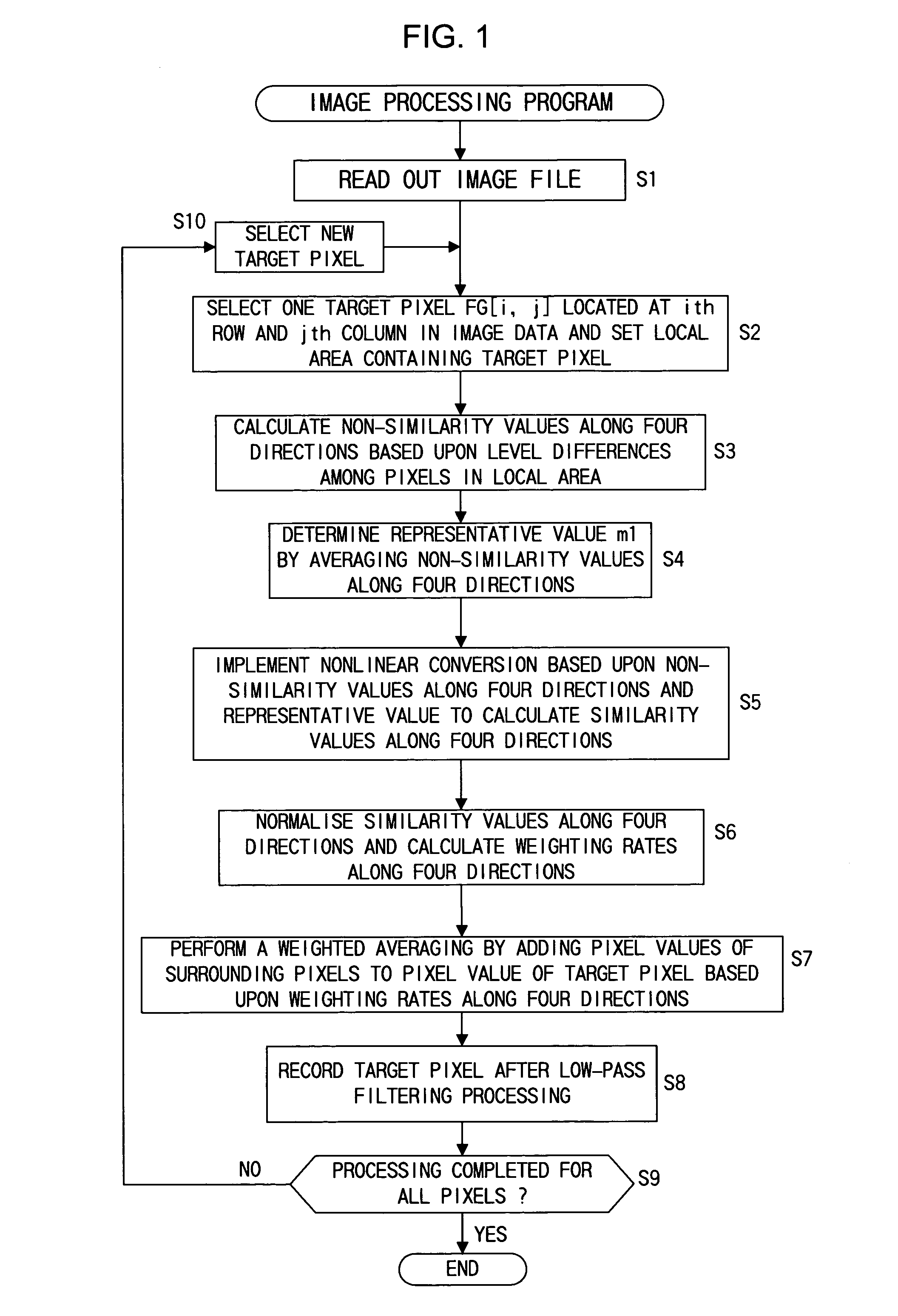
[0076]FIG. 1 is a flowchart of the operating procedure of this image processing program. The following is an explanation of the operation performed in the image processing in the first embodiment given in reference to the operating procedure shown in FIG. 1. First, the computer reads out an image file to undergo the processing, and opens and stores the image data to undergo the processing in memory (step S1). The image processing is performed on single-color image data opened in the memory in this ...

second embodiment

[0101]The second embodiment relates to an electronic camera that processes captured images through an image processing method similar to that in the first embodiment. FIG. 4 is a block diagram illustrating the structure of an electronic camera 11 in the second embodiment.

[0102]In FIG. 4, a taking lens 12 is mounted at the electronic camera 11. A light-receiving surface of an image capturing element 13 is set in the image space of the taking lens 12. RGB image data output by the image capturing element 13 are digitized via an A / D conversion unit 14, and are then input to an image processing unit 15 constituted of a microprocessor. A read only memory 17, an image memory 18 and the like are connected to the image processing unit 15 via a data bus 16. An image processing program is recorded in the read only memory 17. The image processing unit 15 reads out and executes this image processing program.

[0103]FIG. 5 is a flowchart of the operating procedure adopted in the image processing pr...

third embodiment

[0153]The image processing method in the third embodiment is characterized in that at least two types of color information are used in similarity judgment. The following is an explanation of the operation performed to calculate first similarity values in the image processing in the third embodiment.

[0154]In the third embodiment, color information corresponding to three planes constituted of R, G and B is prepared for the calculation of the first similarity values. It is to be noted that if color information corresponding to three planes R, G and B is not available, the interpolation processing is performed first to obtain color information corresponding to three planes R, G and B.

[0155]In the third embodiment, the first similarity values for a pixel at an ith row and a jth column are calculated by using the color information corresponding to the three planes R, G and B thus obtained in the following expressions (110˜113).

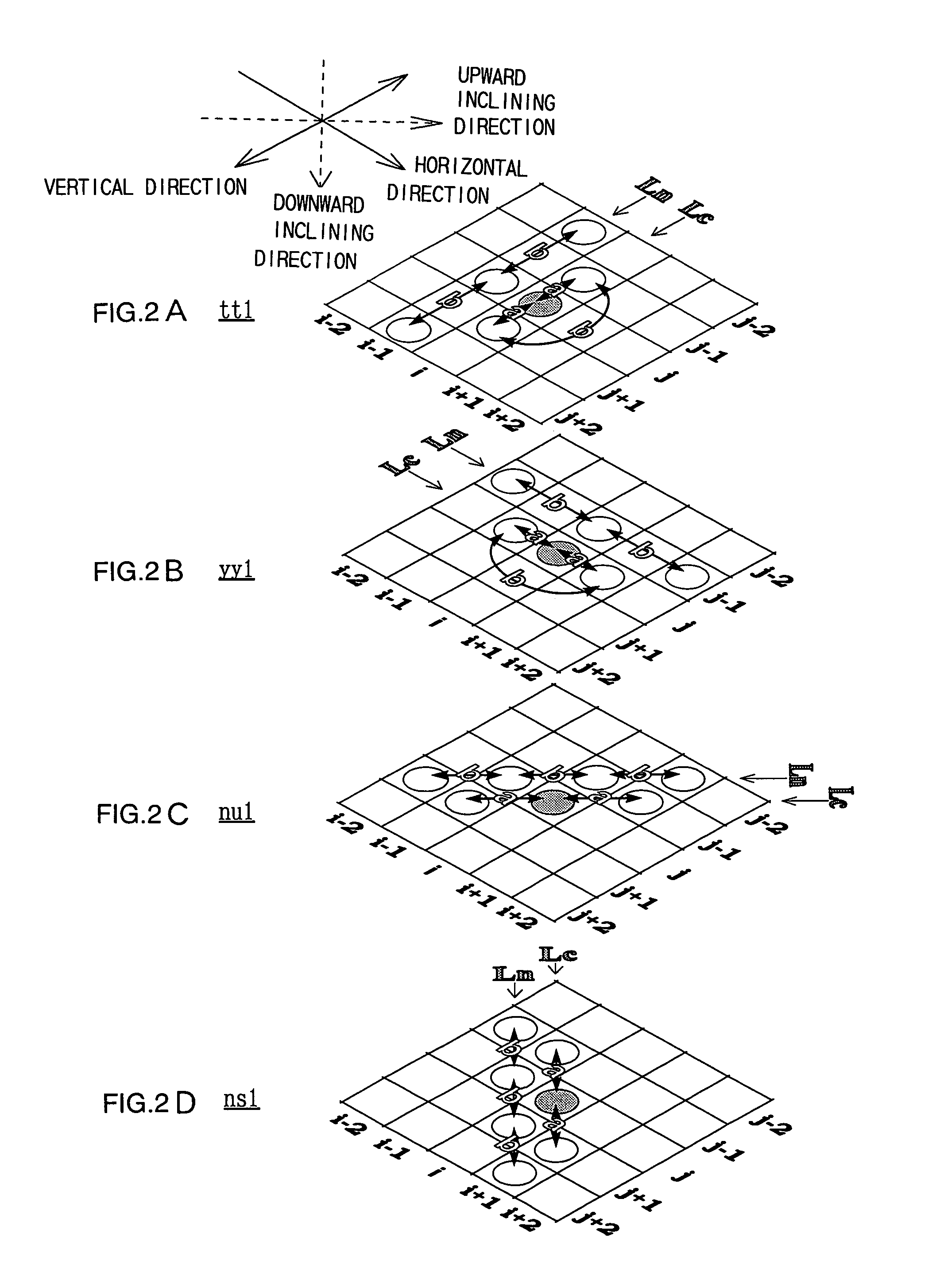
First similarity value along the vertical direction tt1:

tt1=a×...


PUM


Abstract

First similarity values along at least four directions are ascertained within a local area containing a target pixel and weighted averaging is performed by adding the pixel values of pixels around the target pixel value to the pixel value of the target pixel, adding weight along a direction having a small first similarity value (along a direction manifesting a high degree of similarity). By incorporating the pixel value level differences among a plurality of pixels on adjacent lines extending adjacent to the target pixel into the first similarity values, it becomes possible to effectively remove jaggies that are difficult to eliminate in the prior art. Furthermore, by making a judgment on degrees of similarity by incorporating color information such as characteristics differences among different color pixels, a more accurate judgment can be made with regard to the image structure to enable very accurate direction-dependent low-pass filtering.

Description

BACKGROUND OF THE INVENTION[0001]1. Field of the Invention[0002]The present invention relates to an image processing method that may be adopted to perform low-pass filtering processing on image data obtained by performing an image capturing operation at an image capturing element in a digital still camera or the like. The present invention also relates to a recording medium that stores an image processing program utilized to implement the image processing method on a computer and a data signal used to transmit the image processing program via a transmission line. Furthermore, the present invention relates to an image capturing apparatus and an electronic camera that executes the image processing method.[0003]2. Description of the Related Art[0004]In the known art, noise in image data is usually removed by performing low-pass filtering processing of the image data. However, while a noise removal effect is achieved through normal isotopic filtering processing, i.e., through filtering ...

Claims


Application Information

Patent Timeline
IPC IPC(8): G06K9/40G06T3/40G06T5/20G06T5/00H04N1/409H04N5/205H04N5/243H04N9/07H04N9/64H04N101/00
CPCG06T3/4015H04N1/409G06T5/20G06T5/002G06T2207/20192G06T2207/10024
Inventor UTAGAWA, KEN
Owner NIKON CORP
Why Eureka
Try Eureka