Plumbing fitting cover cap retention

a technology of retaining structure and plumbing fitting, which is applied in the field of bath waste plumbing equipment, can solve the problems of not having a prior equipment which incorporates the holding structure of the cover, and achieve the effect of preventing inadvertent access and reducing access

Inactive Publication Date: 2006-03-28
WATERTITE PRODS
View PDF3 Cites 13 Cited by
  • Summary
  • Abstract
  • Description
  • Claims
  • Application Information

AI Technical Summary

Benefits of technology

[0007]The cover is typically positioned to resist inadvertent rotation and / or loosening.
[0008]It is another object to provide for ease of manipulation of the retainer (as for example into or out of operating position). this may be facilitated by providing a slot in the cover, a bridge extending across the slot, and the retainer carried by the bridge to project toward and to penetrate a local portion of the grooving, such a threading, on the tubular terminal.
[0009]It is another object to provide the bridge to extend in the plane of the slot, or offset relative to that plane, to diminish easy access to the retainer in the form of a set screw, thereby to prevent inadvertent access to and loosening of the set screw, as for example during cleaning of such plumbing.

Problems solved by technology

Also, no prior equipment of which we are aware incorporates the cover holding structure as will appear.

Method used


Image

  • Plumbing fitting cover cap retention
  • Plumbing fitting cover cap retention
  • Plumbing fitting cover cap retention

Examples


Embodiment Construction

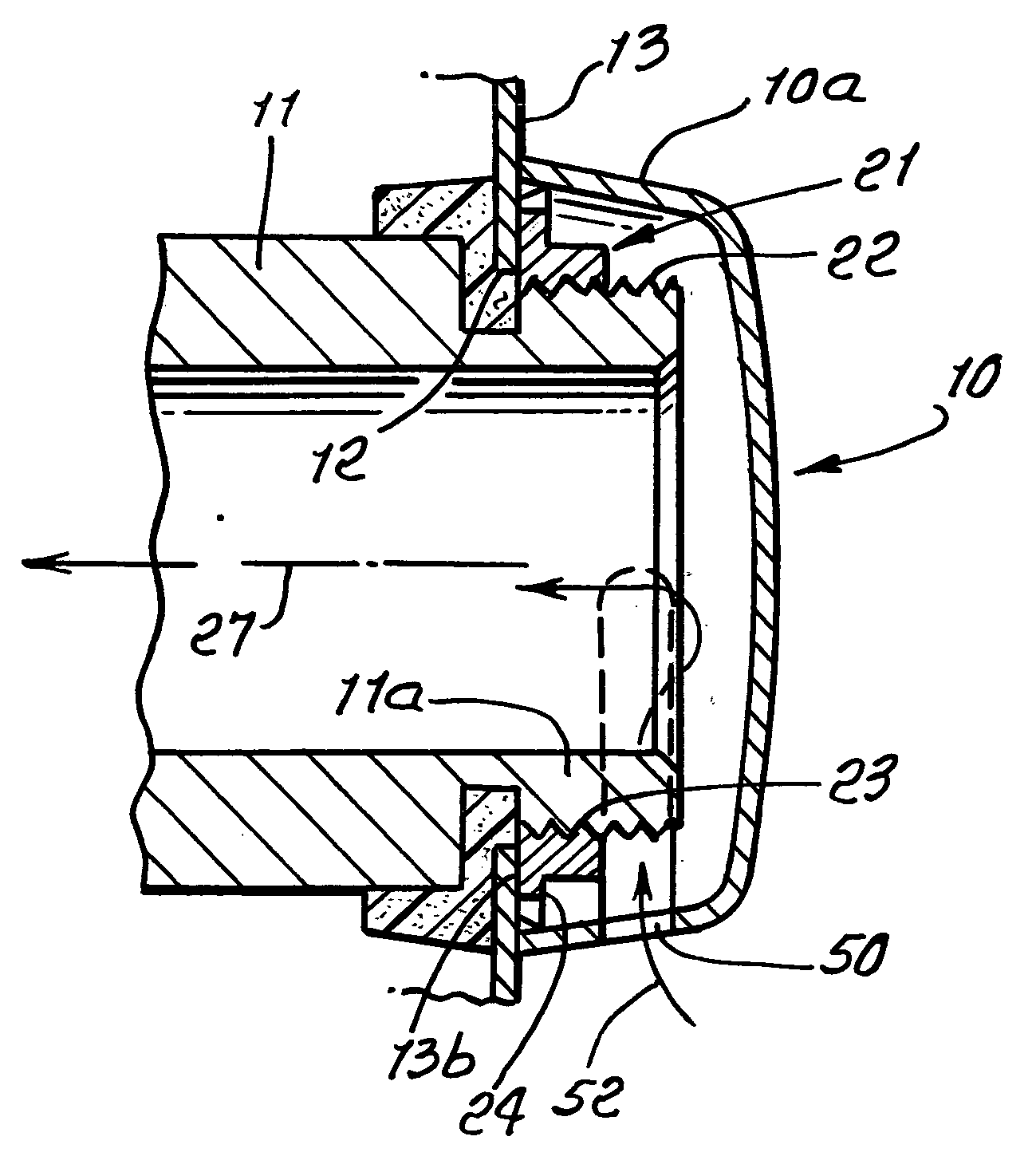
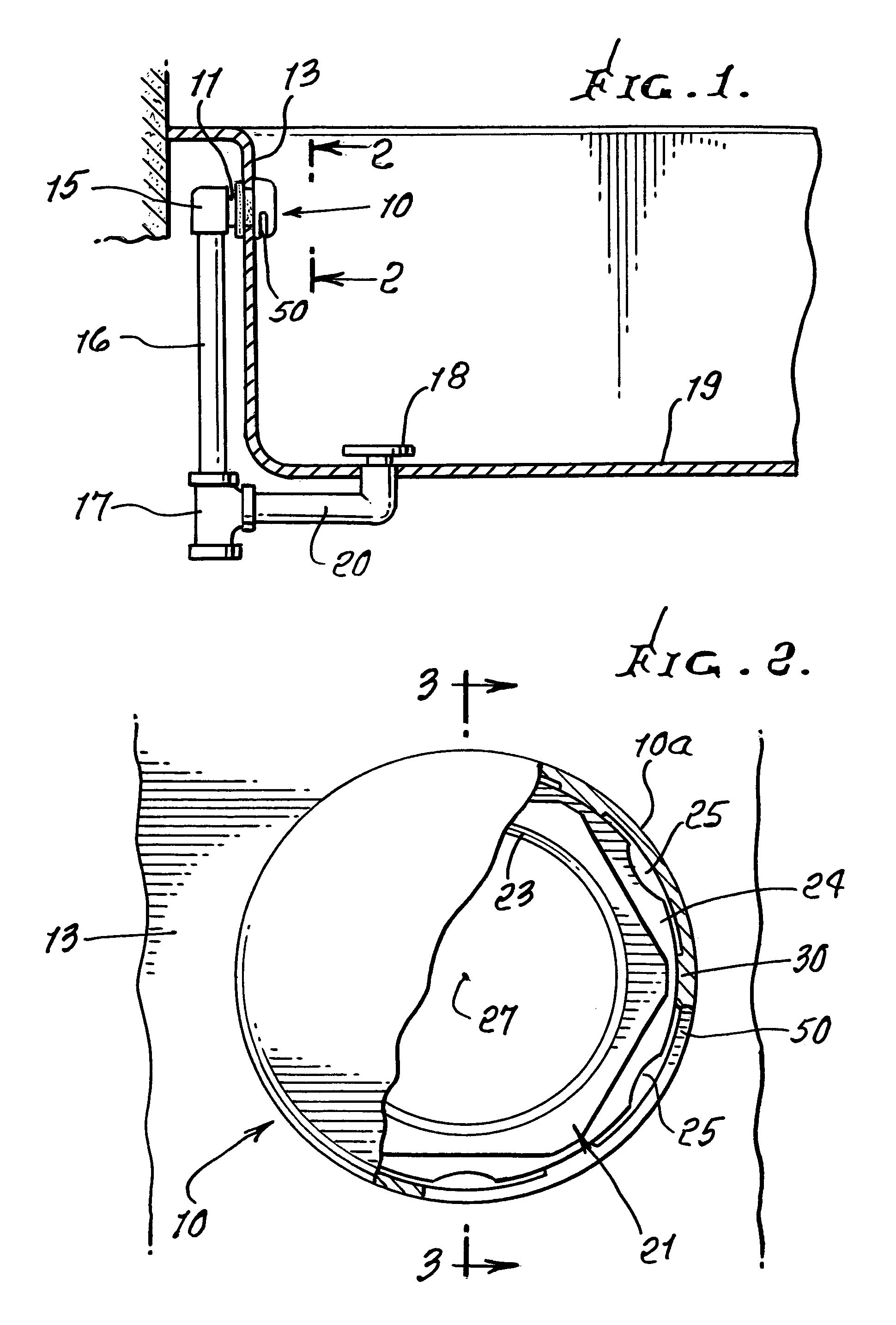
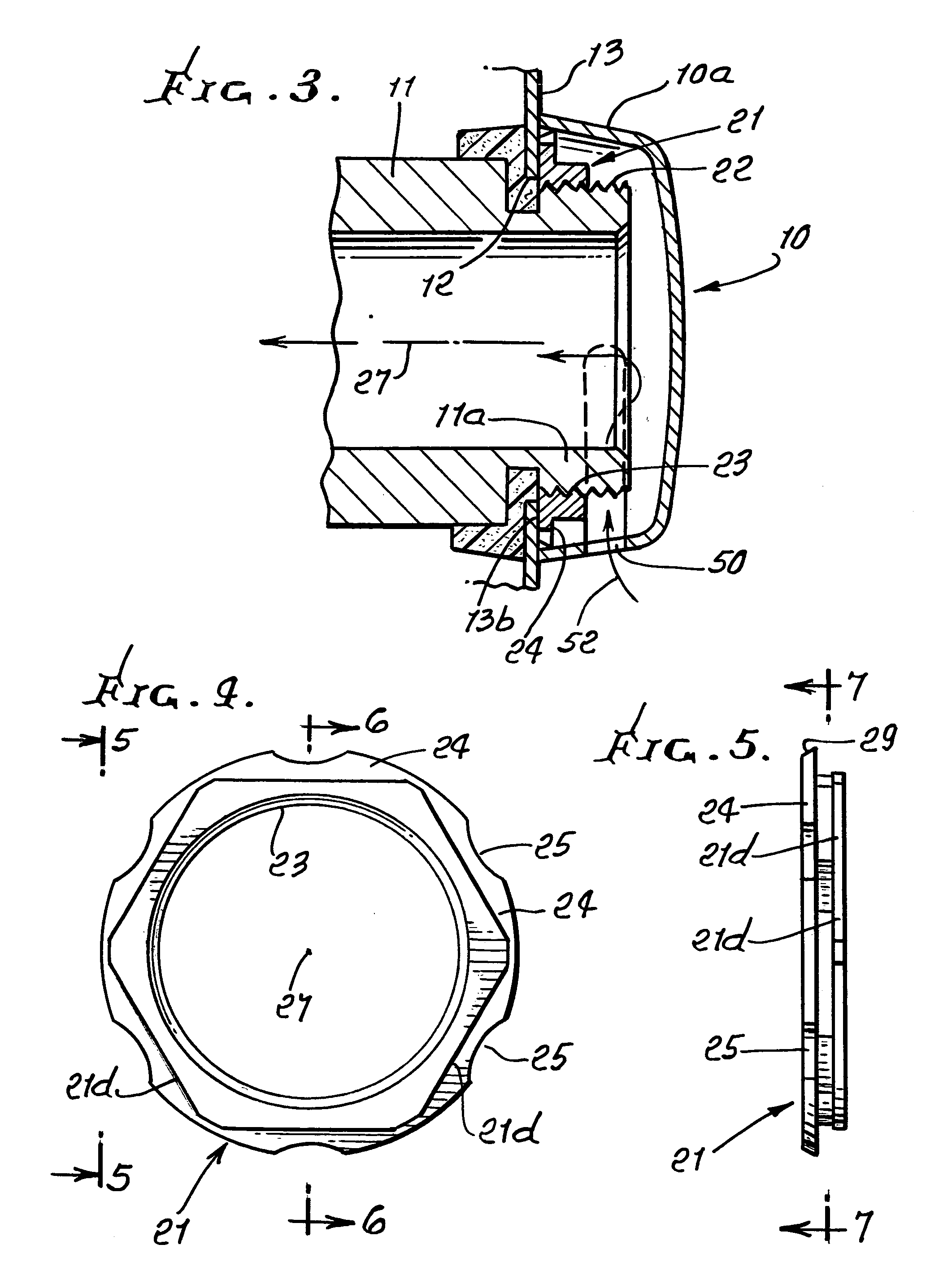
[0041]FIGS. 1 and 3 show a cover cap 10 retained in position to cover a tubular terminal 11a of a plumbing line 11, projecting at or through an opening 12 in a bath or shower wall 13. A bath wall is illustrated, but is also representative of a shower wall. Merely for purposes of illustration, waste water plumbing line 11 may be connected by elbow 15 to a vertical duct 16, to which a tee 17 is connected. An outlet 18 at the tub or shower bottom wall 19 is also connected to the tee, as by waste line 20.

[0042]As shown in FIG. 3, a retainer ring 21 is fitted on terminal 11a. Such fitting may incorporate external threading 22 on 11a, and internal threading 23 on the ring, whereby the ring can be tightened toward wall 13, to frictionally position the ring adjacent the wall, as shown at 13b. FIG. 4 shows wrench flats 21d circularly spaced apart on the ring 21, and engageable by a wrench to facilitate such tightening.

[0043]In accordance with an important feature of the invention, the prefer...


PUM


Abstract

A plumbing fitting attachable to a wall that defines an opening, comprising a tubular part sized to project through an opening, there being grooving associated with the part; a cover extending in registration with the grooving; and a retainer caused by the cover and projecting to locally engage the grooving, thereby to position the cover in relation to the grooving.

Description

[0001]This application is a continuation-in-part of prior U.S. application Ser. No. 10 / 112,844, filed Mar. 28, 2002 now U.S. Pat. No. 6,618,875.BACKGROUND OF THE INVENTION[0002]This invention relates generally to bath waste plumbing equipment, and more particularly retention of waste water outlet covers to terminals or outlets of plumbing fittings, as well as provision and use of caps for pressure testing of plumbing lines leading to such outlets.[0003]There is continual need for improvements in such bath waste plumbing equipment, facilitating ease of application of such outlet covers to plumbing terminals as at bath or shower walls and removal of such covers; and there is need for equipment facilitating pressure testing of such plumbing lines leading to such terminals. No prior equipment of which we are aware incorporates the novel and highly useful cover and mounting structure of the present invention, or its functioning and improved results obtained. Also, no prior equipment of w...

Claims


Application Information

Patent Timeline
Patent Type & Authority Patents(United States)
IPC IPC(8): E03C1/244E03C1/24
CPCE03C1/24
Inventor OROPALLO, ROBERT A.OROPALLO, JR., ANTHONY
Owner WATERTITE PRODS
Why Eureka
Try Eureka