Beam winding apparatus

a technology of winding apparatus and beam, which is applied in the direction of beaming machines, manufacturing tools, transportation and packaging, etc., can solve the problems of uniform shrinkage from yarn to yarn or from one section of yarn to another, and the set-up process is both costly and time-consuming

Active Publication Date: 2006-03-28
HUNTER DOUGLAS INC
View PDF49 Cites 6 Cited by
  • Summary
  • Abstract
  • Description
  • Claims
  • Application Information

AI Technical Summary

Benefits of technology

[0014]In yet another embodiment, the beam winder is comprised of an alignment section for aligning a plurality of continuous yarns in a parallel planar relationship. The beam winder also includes a shrink section which is adapted to receive the aligned planar yarns, apply a first tensioning force to the yarns, and shrink the yarns. A winding section is also provided to receive the aligned yarns from the shrink section, apply a second tensioning force that is greater than the first tensioning force to the yarns, and finally, wind the yarns onto a beam. The beam winder is also configured to prevent the transfer of the second tensioning force from the portion of the aligned planar yarns in the winding section to the portion of the aligned planar yarns in the shrink section.

Problems solved by technology

Given the hundreds of spools typically utilized, the setup process is both costly and time consuming.
Separate preshrinking operations add to the cost of the products produced from the yarn sheet and depending on how the preshrink process is performed, the shrinkage may not be uniform from yarn to yarn or from one section of a yarn to another.
If the constituent fibers of yarn sheet have not been preshrunk, they can shrink during the lamination process and can distort the weft fibers or non-woven mat to which they are adhesively attached resulting in non-woven fabrics that are not aesthetically acceptable.
Further, even when the yarn sheet has been preshrunk, non-uniform, unacceptable non-woven fabrics can result, if the yarns comprising the yarn sheet were not shrunk uniformly.

Method used


Image

  • Beam winding apparatus
  • Beam winding apparatus
  • Beam winding apparatus

Examples


Embodiment Construction

Definitions

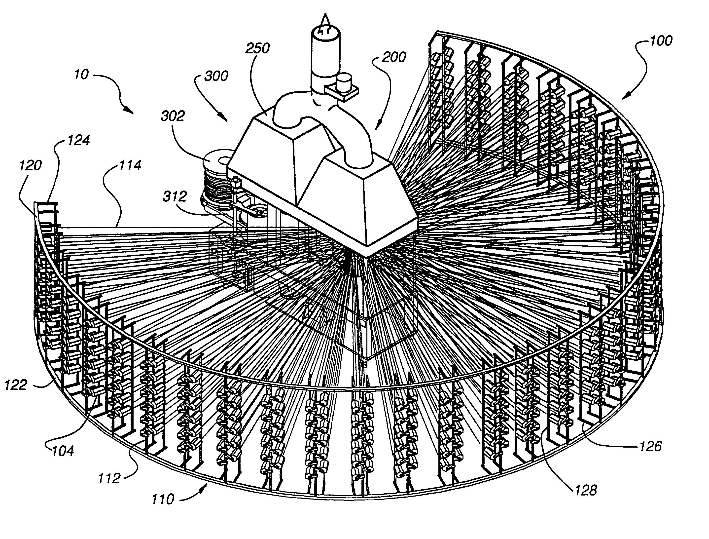
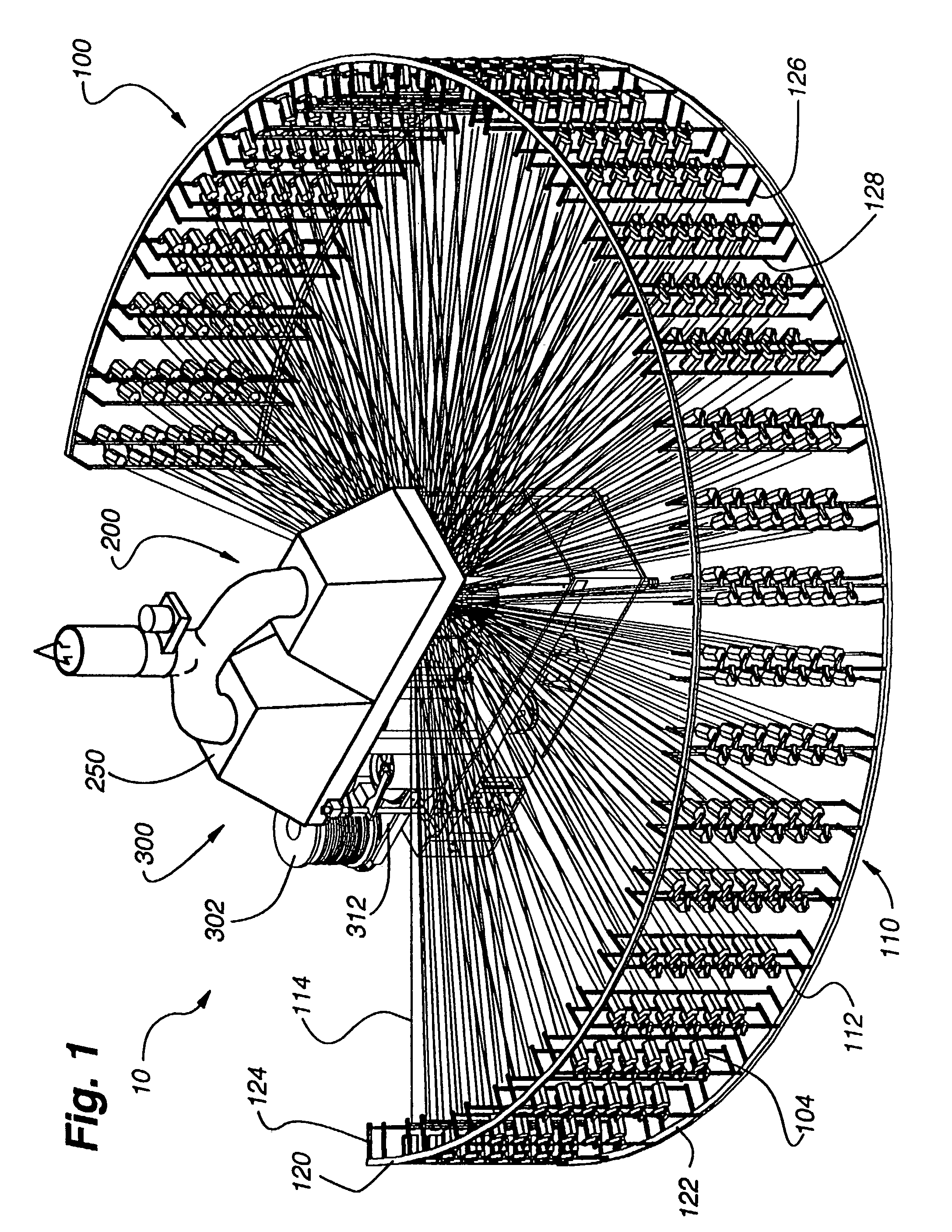
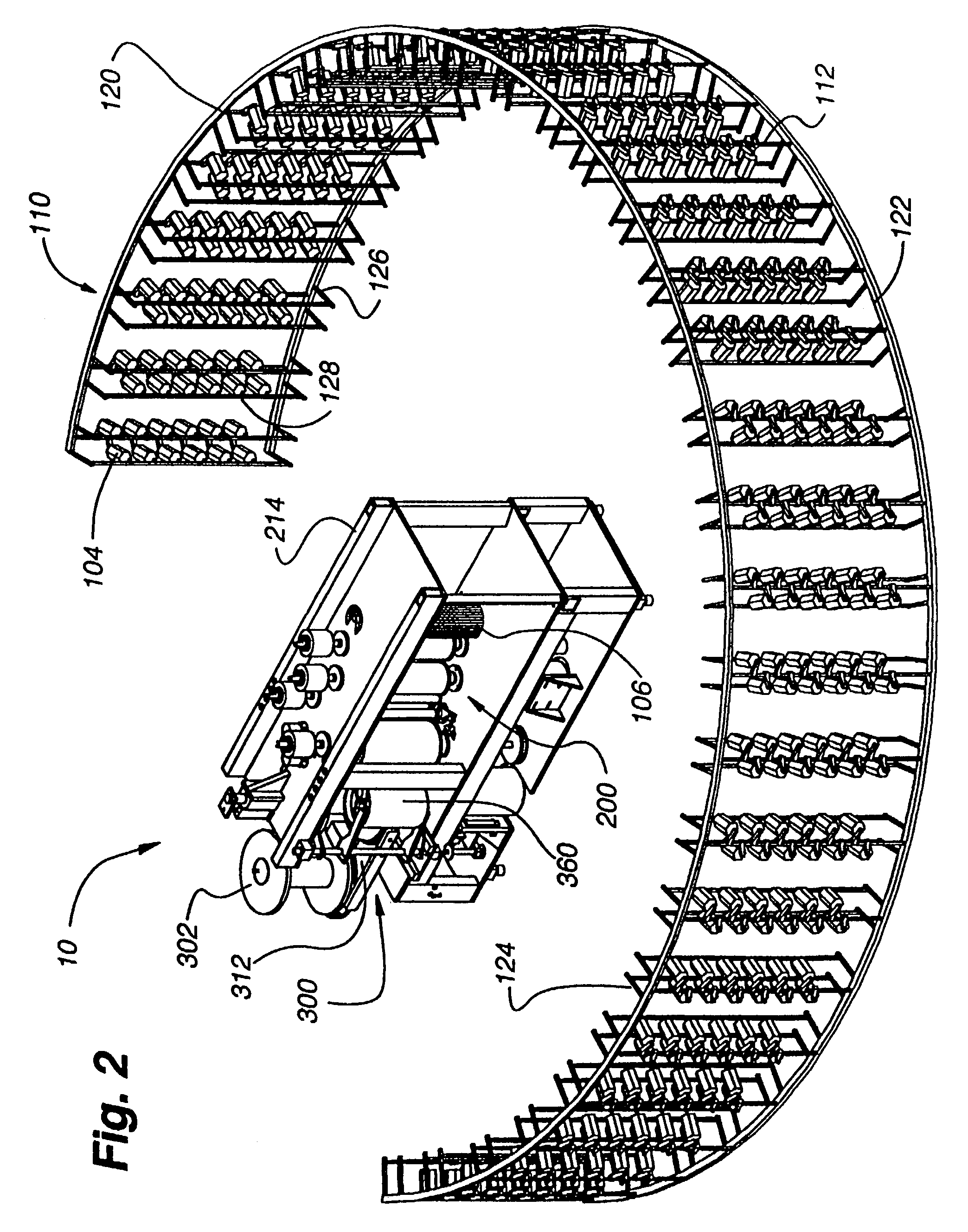
[0043]Beam: As used herein, a beam refers to any spool that is typically, but not necessarily, cylindrically-shaped that may have top and bottom flanges on which the plurality of aligned yarns of the beam winder are wound.

[0044]Yarn: As used herein, a yarn is a continuous strand of one or more fibers or filaments made from any suitable organic or inorganic, natural or synthetic material. Unless otherwise specifically indicated the term “yarn” is not limited to strands that are spun from a plurality of filaments.

[0045]Yarn Sheet: As used herein, a yarn sheet refers to the plurality of aligned planar yarns produced during the beam winding process.

[0046]Spool: As used herein, spool refers to any article adapted to hold a quantity of continuous yarn. Typically, yarn is wound onto a spool.

[0047]Comb: As used herein, a comb refers to a portion of the beam winder that acts to align the plurality of yarns that pass through it in a parallel non-overlapping relationship along a sin...


PUM

PropertyMeasurementUnit
temperatureaaaaaaaaaa
shrinkageaaaaaaaaaa
distanceaaaaaaaaaa

Abstract

An apparatus and method for winding a sheet of aligned parallel yarns onto a beam is described. The beam winder utilizes a circularly arced yarn spool rack that feeds each yarn to an alignment comb through associated guide tubes. The distance between each spool of yarn and the alignment comb is substantially the same for all spools of yarn, thereby equalizing the force necessary to pull them to the comb. Next, the aligned sheet of material is preshrunk using heated rollers and wound onto a beam. Multiple speed controlled stepper motors are utilized to maintain a constant low level of tension in the sheet during the shrinking process. After shrinkage, the tension level of the yarn sheet is increased as it is wrapped onto the beam. A turntable that supports two or more beams is provided to facilitate the rapid switching of beams once one beam has become full.

Description

CROSS REFERENCE TO RELATED APPLICATION[0001]This application is a nonprovisional and claims priority to U.S. Provisional Application Ser. No. 60 / 385,694 (the '694 application), filed Jun. 3, 2002. The '694 application is hereby incorporated by reference as though fully set forth herein.BACKGROUND OF THE INVENTION[0002]1. Field of the Invention[0003]This invention relates generally to a textile fabrication apparatus, and more specifically to a beam winder apparatus for aligning and winding a plurality of textile yarns, threads or filaments on a spool or beam.[0004]2. Description of Background Art[0005]An apparatus for winding a plurality of unidirectionally aligned threads, yarns or filaments onto a beam is well known in the art. This type of apparatus is typically referred to as a “beam winder” or a “warping machine.” (the aligned yarns often form the warp direction of a subsequently fabricated fabric). In general, a beam winder (1) unwinds a large number of yarns from spools or bob...

Claims


Application Information

Patent Timeline
Patent Type & Authority Patents(United States)
IPC IPC(8): D02H5/00D02H1/00D02H3/00D02H5/02D02H13/00D02H13/16D02H13/24D02H13/28
CPCD02H1/00D02H13/24D02H5/02D02H5/00
Inventor COLSON, WENDELL B.FOGARTY, DANIEL M.HARTMAN, DAVID P.
Owner HUNTER DOUGLAS INC
Why Eureka
Try Eureka