Product dispensing head and packaging with variable flow

a product dispenser and variable flow technology, applied in the direction of liquid dispensing, closure stoppers, applications, etc., can solve the problems of difficult to obtain a reproducible spray for one or more positions, complicated dispensing head manufacture, and difficult to obtain good spray

Active Publication Date: 2006-03-28
LOREAL SA
View PDF9 Cites 35 Cited by
  • Summary
  • Abstract
  • Description
  • Claims
  • Application Information

AI Technical Summary

Benefits of technology

[0007]It is an object of the invention to provide a dispensing head which can avoid one or more, preferably all, of the drawbacks of the prior art.
[0009]Another object of the invention is also to provide a dispensing head that is simple and inexpensive to produce.
[0010]A further object of the invention is to provide a dispensing head that is capable of switching readily from one dispensing position to another dispensing position.
[0015]The presence of an elastically deformable connecting arrangement makes it possible to produce a conduit by a molding process from a single piece with the attachment arrangement, while being capable of moving relative to the attachment. Such a part is simple and inexpensive to produce.
[0016]Furthermore, the dispensing head is simple and inexpensive to make in that it requires only a single spray orifice formed in the actuating means, and in that the two passages of different cross-section are easy to produce as they can be formed during molding of the conduit. Advantageously, the connecting arrangement is preferably elastically deformable so that it reverts to an initial position when the load causing deformation is removed.
[0018]The connecting arrangement allows movement of the conduit in response to actuation. In a preferred embodiment, the connecting arrangement is formed by a transverse wall relative to axis X, with the wall corrugated. This configuration of the wall enables it to deform easily and to revert easily to its initial position.

Problems solved by technology

However, the necessary clearance between the nozzle and each centerpost to allow the push button to rotate between the three positions prevents the nozzle from being correctly positioned at each centerpost so that it is difficult to obtain a good spray.
Furthermore, such a clearance makes it impossible to align the nozzle in an identical manner with the different centerposts so that it is very difficult to obtain a reproducible spray for one or more of the positions.
This configuration requires two spray orifices which complicates the manufacture of the dispensing head as such orifices are more difficult to make than a simple hole.

Method used


Image

  • Product dispensing head and packaging with variable flow
  • Product dispensing head and packaging with variable flow
  • Product dispensing head and packaging with variable flow

Examples


Embodiment Construction

[0034]Non-limiting examples of the invention will now be described with reference to the drawing figures. It is to be understood, however, that various modifications are possible and the invention is not limited to the specific examples illustrated.

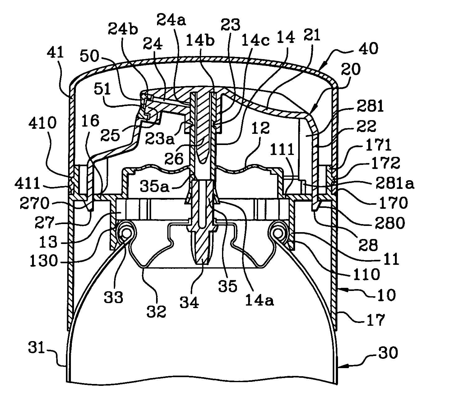
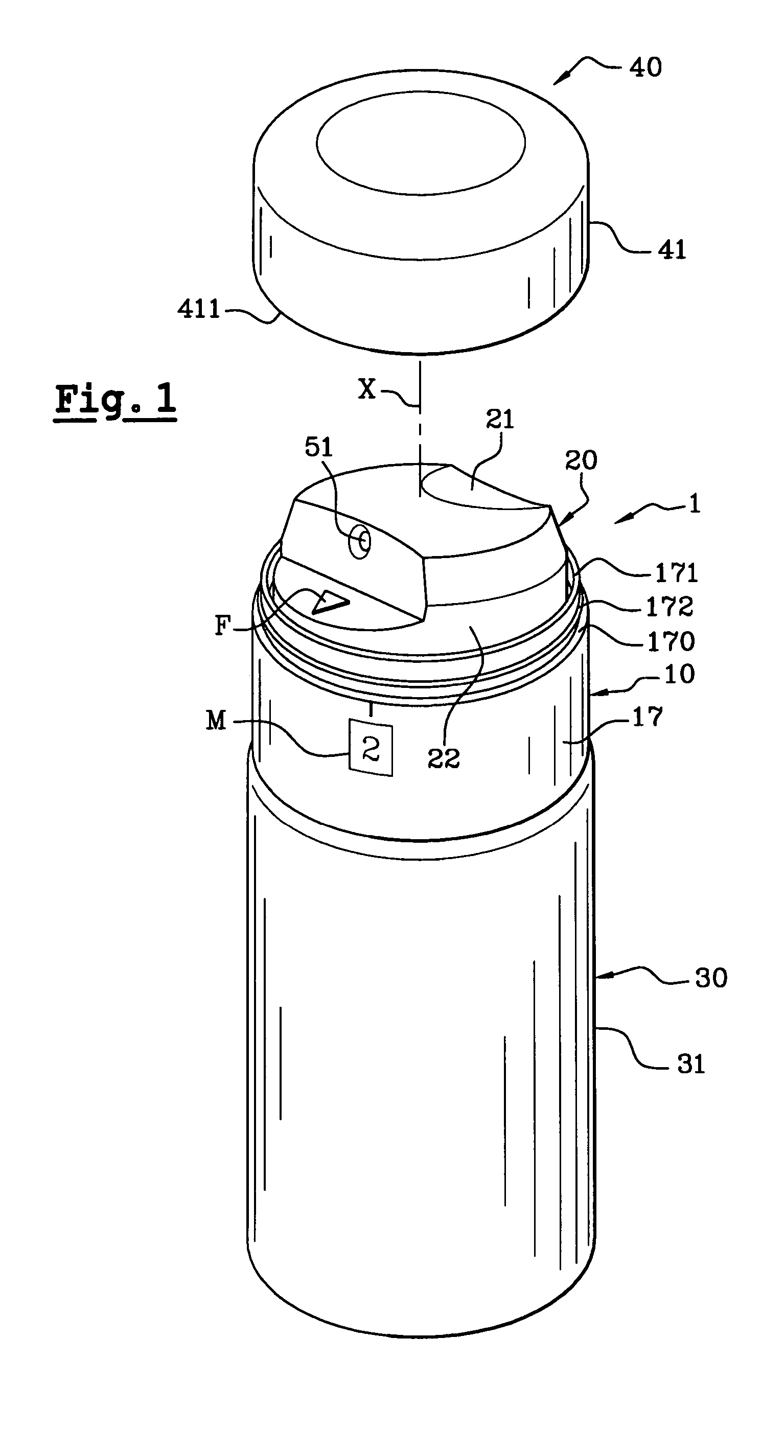
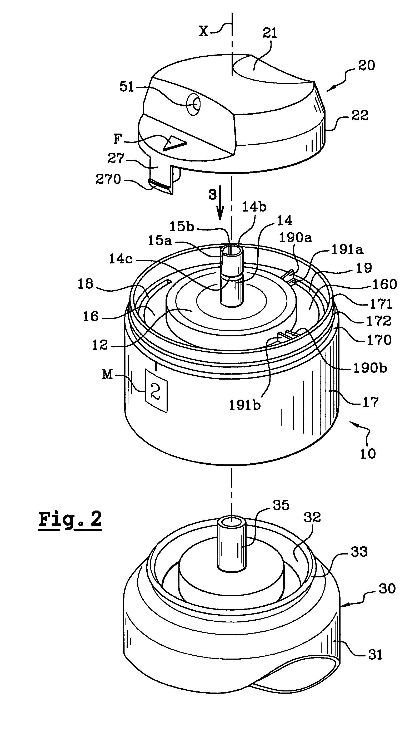
[0035]The packaging and dispensing unit illustrated in FIGS. 1 to 7 is composed of a pressurized container 30, partially illustrated in FIGS. 2, 4, 5 and 7, on which a dispensing head 1 according to the invention is attached and which can be closed by means of a cap 40. The receptacle 30 is formed by a pressurized can having an axis X, formed by a body 31 of cylindrical shape of which the upper end is closed by a collar 32 crimped onto a rolled edge 33 of the receptacle. As noted earlier, however, the container need not be pressurized. In addition, the container could have different shapes and forms.

[0036]The collar 32 is fitted with a valve 34 which includes a hollow valve stem 35 and which can be actuated, for example, by depressing the...


PUM


Abstract

A package for dispensing a product and a dispensing head for such a package are provided. In an illustrated form, the dispensing head has an axis X, designed to actuate a dispensing element mounted on a receptacle to dispense a product contained in the receptacle. A dispensing conduit is capable of communicating with the product inside the receptacle and has at least two passages of different cross-sections. In a preferred form, the conduit is molded as a single piece with the arrangement attaching the head to the receptacle integral therewith via a deformable connection. An actuator arrangement is provided to actuate the dispensing element and to cause the conduit to communicate with the inside of the receptacle, with a dispensing orifice formed at the extremity of a channel preferably having a length greater than the diameter of the dispensing orifice. The actuating arrangement is movable relative to the conduit between at least two positions, a first position in which the dispensing orifice communicates with one of the passages, and a second position in which the dispensing orifice communicates with the other passage.

Description

CROSS-REFERENCE TO RELATED APPLICATIONS:[0001]This document claims priority to French Application No. 02 09448, filed Jul. 25, 2002 and U.S. Provisional Application No. 60 / 407,297, filed Sep. 3, 2002, the entire content of which is hereby incorporated by reference.FIELD OF THE INVENTION[0002]The present invention relates to a product dispenser and packaging in which a dispensing head for the product is designed to actuate a dispensing element mounted on a receptacle, preferably a valve mounted on a pressurized container, for dispensing a product contained in the receptacle. In particular, the invention provides a dispensing head enabling the product to be dispensed with at least two different flowrates.BACKGROUND OF THE INVENTIONDiscussion of Background[0003]Dispensing heads of the general type to which the invention pertains are known, notably in U.S. Pat. Nos. 3,363,968 and 3,703,994.[0004]The dispensing head described in U.S. Pat. No. 3,363,968 utilizes a collar attached to the r...

Claims


Application Information

Patent Timeline
Patent Type & Authority Patents(United States)
IPC IPC(8): B65D83/00B65D83/14B65D83/16
CPCB65D83/44B65D83/205
Inventor LASSERRE, PIERRE-ANDRESANCHEZ, MARCELDALSANT, GUISEPPE
Owner LOREAL SA
Why Eureka
Try Eureka