Paper treating unit and image forming system using the same

Active Publication Date: 2006-03-28
RICOH PRINTING SYST
View PDF12 Cites 8 Cited by
  • Summary
  • Abstract
  • Description
  • Claims
  • Application Information

AI Technical Summary

Benefits of technology

[0007]The present invention has been achieved in the light of the above-mentioned problems, and it is an object of the invention to provide a paper exhausting unit in which the paper of any size can be loaded reliably and aligned excellently.
[0030]The invention may provides an image forming apparatus system, including an image forming apparatus that forms an image on a paper and the paper treating unit. Accordingly, the paper exhausted from the image forming apparatus can be loaded and aligned excellently.

Problems solved by technology

This operation applies a large load on each guide plate and a driving member for driving each guide plate, possibly causing a failure.

Method used


Image

  • Paper treating unit and image forming system using the same
  • Paper treating unit and image forming system using the same
  • Paper treating unit and image forming system using the same

Examples


Embodiment Construction

[0041]The preferred embodiments of the present invention will be described below in detail with reference to the accompanying drawings.

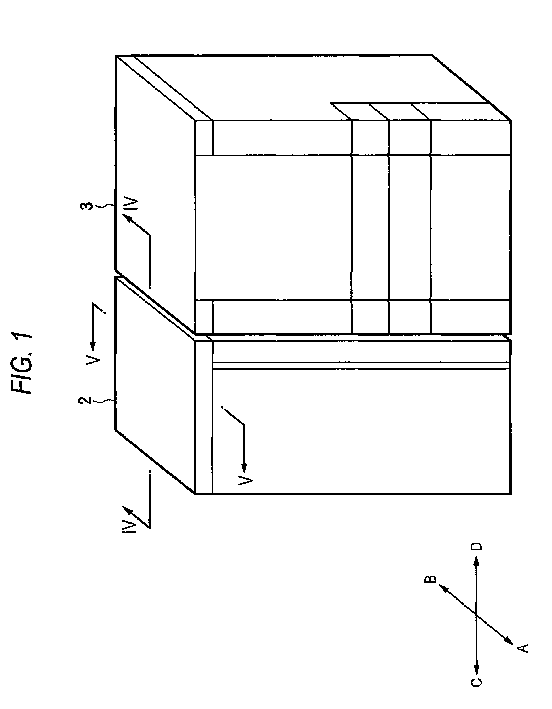
[0042]FIG. 1 is a view showing a printing system according to an embodiment of the present invention. A printer 3 as an image forming apparatus and a paper exhausting unit 2 disposed adjacent to the printer 3 are illustrated in FIG. 1. In the following description, an operator side is defined as the fore side of FIG. 1 (Arrow A at FIG. 1), a counter operator side as the rear side (Arrow B at FIG. 1), a paper proceeding direction as the left direction (Arrow C at FIG. 1), and a counter paper proceeding direction as the right direction (Arrow D at FIG. 1).

[0043]The printer 3 is the image forming apparatus for forming a predetermined image on the paper, using the toner. The printer 3 delivers the printed paper via an exhausting port, not shown, to a paper exhausting unit 2. A paper exhausting sensor, not shown, is attached near the exhausting port of th...


PUM


Abstract

A paper treating unit includes: a paper loading table for loading paper; a first paper aligning member that regulates position of the paper by sliding back and forth in the paper proceeding direction; a second paper aligning member disposed upstream of the first paper aligning member in the paper proceeding direction to regulate the position of the paper in the paper proceeding direction; a third paper aligning member disposed along the paper proceeding direction to regulate the position of the paper in a width direction perpendicular to the paper proceeding direction by sliding back and forth in the direction perpendicular to the paper proceeding direction; and a position detecting unit that detects the position of the first to third paper aligning members. The first and third paper aligning members are disposed independently of the paper loading table.

Description

BACKGROUND OF THE INVENTION[0001]1. Field of the Invention[0002]The present invention relates to a paper treating unit such as a paper exhausting unit connected at the latter stage of an image forming apparatus such as a copier or a laser beam printer.[0003]2. Background Art[0004]The paper exhausting unit is provided at the latter stage of the image forming apparatus to enable the printed paper from the image forming apparatus to be loaded in order. This paper exhausting unit is required to align the paper in order in a paper proceeding direction and a perpendicular direction (paper width direction) to the paper proceeding direction in consideration of the post-processing such as bookbinding.[0005]In JP-A-11-138966, there was disclosed a paper receiving unit for aligning the printed paper. This paper receiving unit comprises a pair of width guide plates arranged in parallel to the paper proceeding direction on a paper receiving tray, and a stop guide plate against which the front ed...

Claims


Application Information

Patent Timeline
Patent Type & Authority Patents(United States)
IPC IPC(8): B65H31/26B65H9/10B65H31/36B65H31/38
CPCB65H9/101B65H31/36B65H2511/20B65H2801/06B65H2220/01B65H2220/11
Inventor SHIRAISHI, TATSUYAHASHIMOTO, YASUSHI
Owner RICOH PRINTING SYST
Why Eureka
Try Eureka