
Porous material for channeling ink in an ink cartridge and method for channeling ink

a technology of porous material and ink cartridge, which is applied in the field of porous material for channeling ink in ink cartridge and channeling method, can solve the problems of time-consuming and tedious process, difficult design alteration, and difficult design alteration, and achieve the effects of reducing residual ink, preventing capillary force disruption in some areas of foam material, and reducing porosity locally

Inactive Publication Date: 2006-03-28
PRINTECH INT
View PDF7 Cites 4 Cited by
  • Summary
  • Abstract
  • Description
  • Claims
  • Application Information

AI Technical Summary

Benefits of technology

[0008]The primary object of the invention is to provide a porous material structure that is designed with a protrusive bottom to be squeezed by the ink cartridge when housed in an ink compartment to form an ink gathering zone that has a greater porosity locally. Thereby a greater capillary force is generated to channel the ink contained in the porous material to move towards the ink gathering zone at the bottom of the porous material. Disruption of the capillary force in some areas of the foam material may be prevented. As a result, residual ink may be reduced, and design and mass production adaptability may be enhanced.
[0009]Another object of the invention is to provide an ink channeling method for ink cartridges. A porous material is provided that has a protrusive bottom to be squeezed by the ink cartridge when housed in an ink compartment to form an ink gathering zone at the bottom of the porous material that has a greater porosity locally. Thereby a greater capillary force is generated to channel the ink contained in the porous material to move towards the ink gathering zone at the bottom of the porous material. Disruption of the capillary force in some areas of the foam material may be prevented. As a result, residual ink may be reduced, and design and mass production adaptability may be enhanced.

Problems solved by technology

It is a time-consuming and tedious process.
Design alteration is difficult.
Thus design alteration is difficult.

Method used


Image

  • Porous material for channeling ink in an ink cartridge and method for channeling ink
  • Porous material for channeling ink in an ink cartridge and method for channeling ink
  • Porous material for channeling ink in an ink cartridge and method for channeling ink

Examples


Embodiment Construction

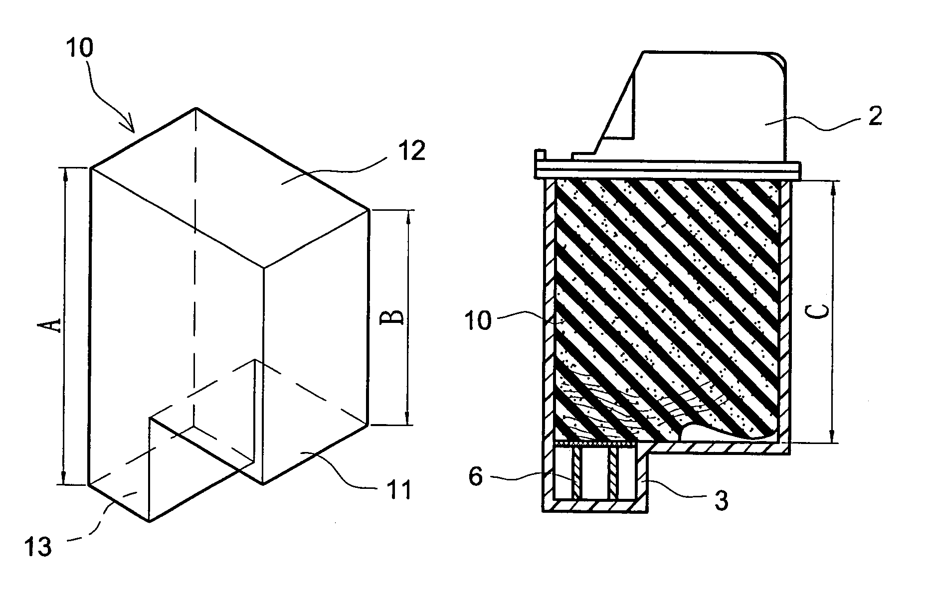
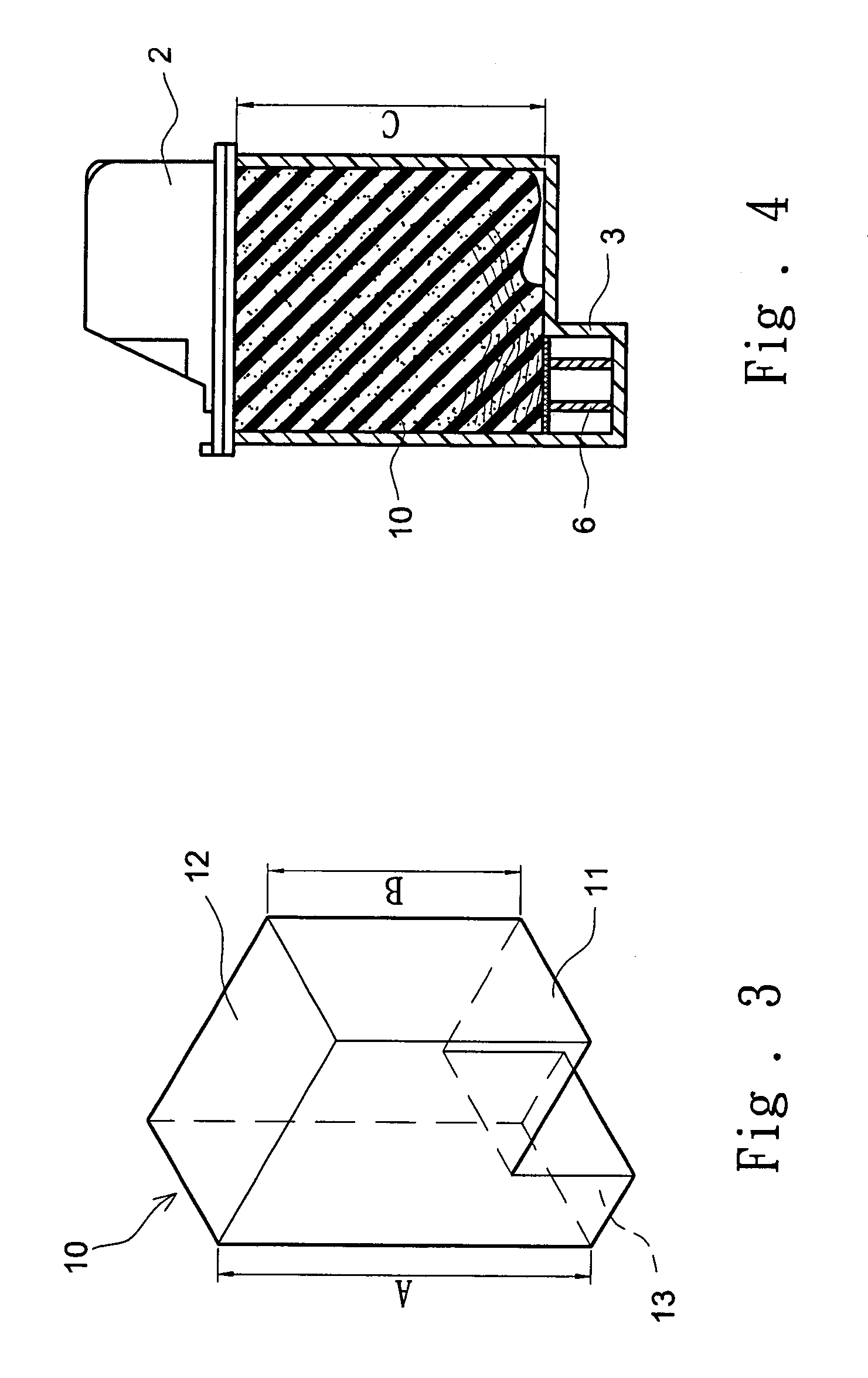
[0022]Referring to FIGS. 3, 4 and 5, the porous material 10 of the invention is contained in an ink compartment 4 of an ink cartridge. The porous material 10 includes a body 11, a top surface 12 and a bottom surface 13 smaller than the top surface 12. The bottom surface 13 is bucking against an inkjet head 3 of the ink cartridge.

[0023]Referring to FIGS. 4 and 5, the porous material 10 is placed in an ink cartridge which includes an inkjet head 3 with a boss 6 not extending into the ink compartment 4. Its bottom surface 13 is bucking against the boss 6 of the inkjet head 3. The height (A) of one side of the body 11 is greater than the height (B) of another side so that it can generate a greater compression ratio when bucking against the boss 6. The height (A) is the height between the top surface 12 and the bottom surface 13. The height (B) of the body 11 is greater than the height (C) of the ink cartridge. After the porous material 10 has been squeezed into the ink compartment 4, a ...


PUM

PropertyMeasurementUnit
heightaaaaaaaaaa
heightaaaaaaaaaa
heightaaaaaaaaaa

Abstract

A porous material for channeling ink in an ink cartridge and a method for channeling the ink includes a porous material housed in an ink compartment of the ink cartridge. The porous material includes a body which has a protruding portion located proximate at the bottom. The bottom surface is bucking the ink cartridge according to the required ink gathering location and is squeezed to form an ink gathering zone that has a higher porosity locally to channel ink movement and reduce residual ink.

Description

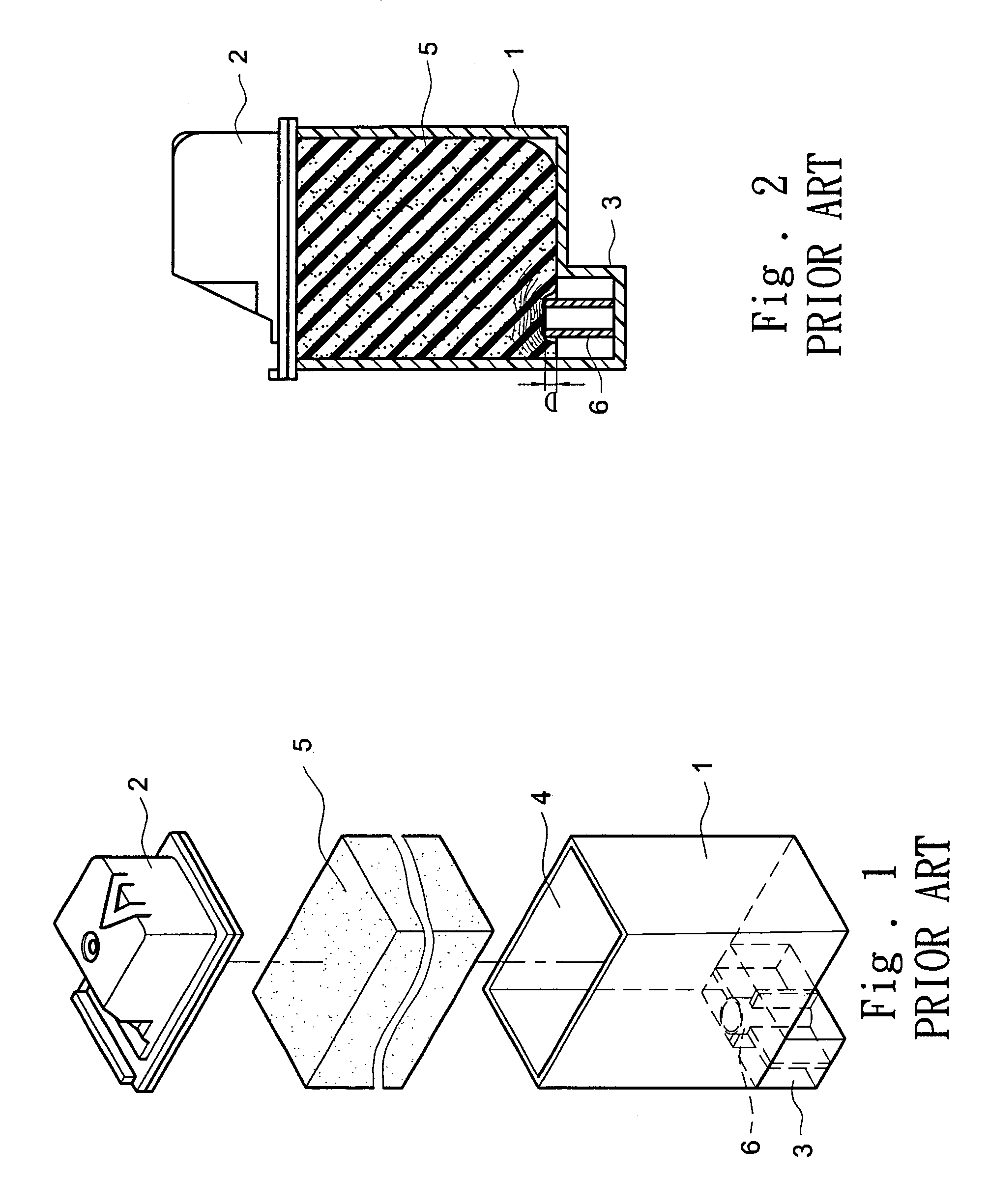
FIELD OF THE INVENTION[0001]The present invention relates to ink cartridges and particularly to an ink channeling design for a porous material contained in an ink compartment of an ink cartridge to adsorb ink.BACKGROUND OF THE INVENTION[0002]Conventional ink cartridges for inkjet printers have an ink containing design which may be classified in three types: foam material, air bag and ink bag. Foam material has good space adaptability and is applicable even in a small space. It also is easy to install. Thus it has attracted a lot of interests in the industry.[0003]Refer to FIG. 1 for the structure of a conventional ink cartridge that uses foam material. It includes a shell 1, a cap 2 located above the shell 1 and an inkjet head 3 located below the shell 1. The shell 1 has an ink compartment 4 to contain foam material 5 and ink. The inkjet head 3 has a boss 6 extending into the ink compartment 4. Conventional foam material 5 usually is a rectangular sponge squeezed into the ink compar...

Claims


Application Information

Patent Timeline
Patent Type & Authority Patents(United States)
IPC IPC(8): B41J2/175
CPCB41J2/17513
Inventor CHOU, CHING-YUTSENG, YING-RAN
Owner PRINTECH INT
Learn More