Distributed dimmable lighting control system and method

a dimmable lighting and control system technology, applied in the direction of photometry, photometry using electric radiation detectors, instruments, etc., can solve the problems of high cost of relamping burnt lamps, high cost of lighting stores and commercial buildings, and high cost of building owners, so as to reduce costs

Active Publication Date: 2006-03-28
UTC CANADA CORP MICRO THERMO TECH DIV
View PDF4 Cites 151 Cited by
  • Summary
  • Abstract
  • Description
  • Claims
  • Application Information

AI Technical Summary

Benefits of technology

[0011]Still another object of the present invention is to log data on the natural lighting contribution and the artificial lighting contribution to produce control reports to better adapt the control system to the conditions of the building.
[0012]Another object of the present invention is to allow a live configuration of the control system to ensure proper lighting at all times.
[0013]Another object of the present invention is to reduce costs by extending periods between relamping.

Problems solved by technology

Lighting stores and commercial buildings is a considerable expense to building owners.
Furthermore, relamping burnt lamps is very expensive and when a lamp is used constantly, it burns faster.

Method used


Image

  • Distributed dimmable lighting control system and method
  • Distributed dimmable lighting control system and method
  • Distributed dimmable lighting control system and method

Examples


Embodiment Construction

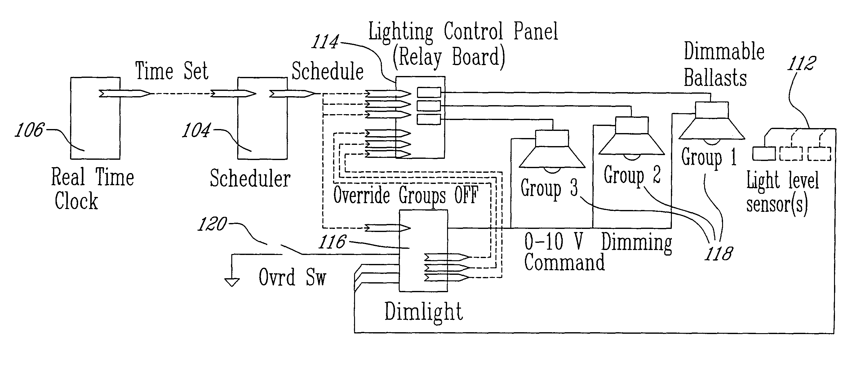
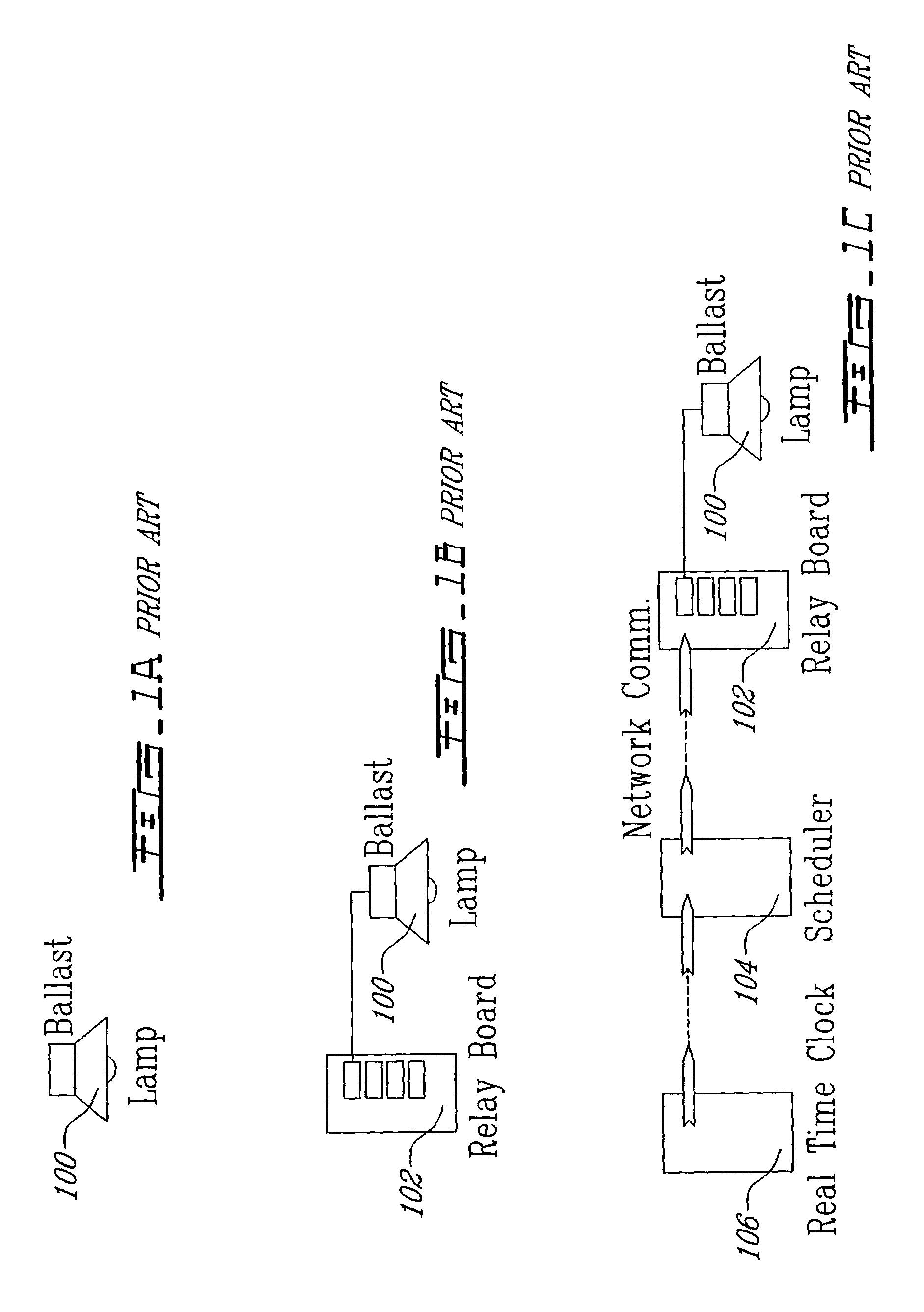
[0039]As shown in FIG. 1, a zone, or building area, is equipped with at least one lamp 100 to light it. Examples of these lamps can be controllable electronic HID Ballast lamps available from Delta Power Supply Inc of Cincinnati, Ohio.

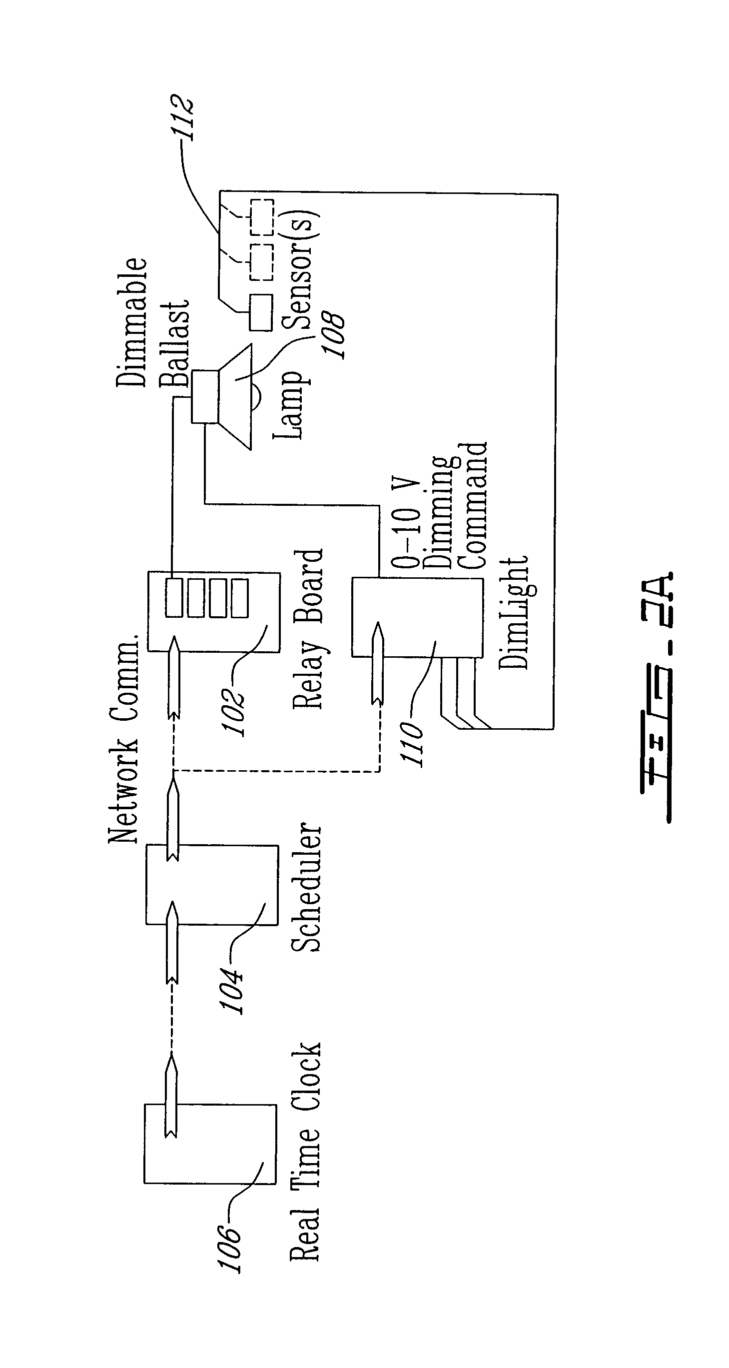
[0040]As shown in FIG. 2, power is applied to the lamp(s) 100 of the zone by energizing a relay mounted in a Lighting Control Panel or Relay Board 102. To turn the light ON, the attendant responsible for this zone must energize the associated relay otherwise the light will be OFF in this zone.

[0041]Normally, the requested state of the light 100 in a zone is controlled according to a schedule specifying at what time the light must be turned OFF or ON. This is done by connecting a scheduler 104 to the Relay Board 102. The scheduler 104 uses a real time clock 106 to ensure proper operation.

[0042]The embodiment of the invention discussed herein uses distributed control technology where instrumentation and control devices can be seen as nodes on a network w...


PUM


Abstract

To reduce energy costs in buildings where there is an input of natural light, a method of maintaining an ambient light intensity in a building area at a predetermined level is proposed. It comprises obtaining an ambient light intensity level for the building area; comparing the ambient level to the predetermined level of light intensity; if the ambient level differs from the predetermined level, calculating an artificial lighting input to be generated in the building area to attain the predetermined level. It can further comprise generating the artificial lighting input in the building area and carrying out the steps of obtaining, comparing and calculating a second time to determine a quality of the calculating and modify the generating.

Description

FIELD OF THE INVENTION[0001]The invention relates to controlling lighting in buildings. More specifically, it relates to controlling the intensity of artificial lighting in buildings where there is an input of natural lighting.BACKGROUND OF THE INVENTION[0002]Lighting stores and commercial buildings is a considerable expense to building owners. Typically, a lighting architecture is designed when the building is built and the lights are either turned on or off by the store manager during operating hours. Most lights are grouped into sections which are turned on or off as a whole. Some lights may have dimmers which allow a store manager to vary the intensity of groups of lights or individual lights.[0003]Some store owners use timers to turn on and off lights, individually or collectively, especially in cases where the lamps need a warm-up delay before turning on completely and a cooling delay when turning off.[0004]Most stores have large windows on at least one side of the building. S...

Claims


Application Information

Patent Timeline
Patent Type & Authority Patents(United States)
IPC IPC(8): H01J40/14H05B37/02H05B39/04H05B41/38H05B41/392
CPCH05B37/0254H05B41/3922H05B39/042H05B47/18
Inventor CLOUTIER, SERGESTRIMBEANU, GABRIEL-ADRIAN
Owner UTC CANADA CORP MICRO THERMO TECH DIV
Why Eureka
Try Eureka