Optical scanning device
a scanning device and optical technology, applied in the direction of measuring devices, instruments, printing, etc., can solve the problem of hard heat generated by mechanical deflectors being transmitted to the housing, and achieve the effect of stable optical scanning without fluctuation
- Summary
- Abstract
- Description
- Claims
- Application Information
AI Technical Summary
Benefits of technology
Problems solved by technology
Method used
Image
Examples
first embodiment
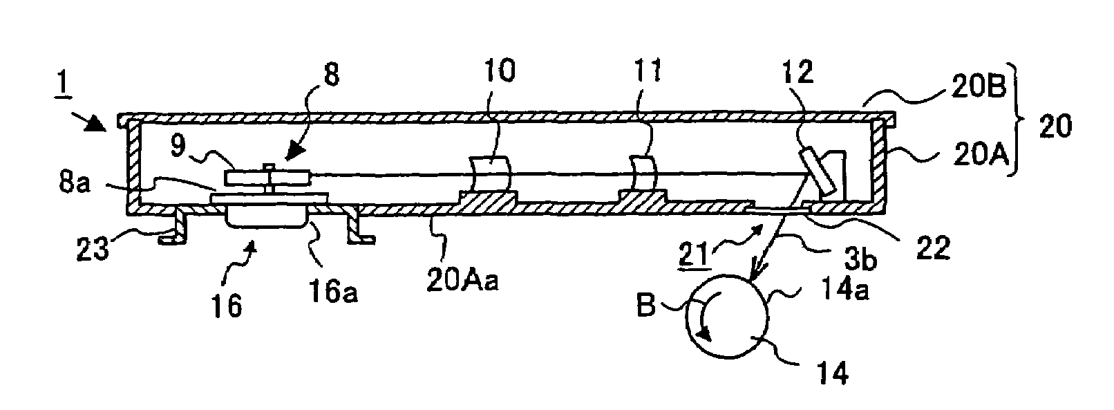
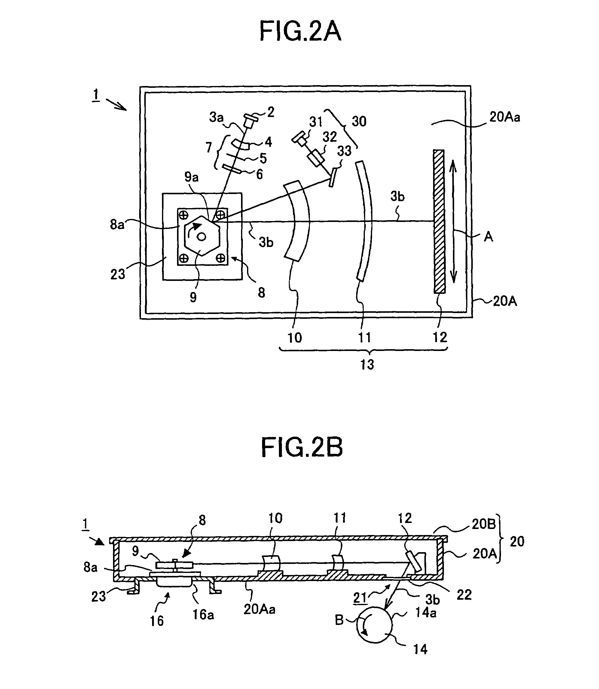
[0044]FIG. 2A shows a plan view (in a state in which a cover 20B is removed from a housing body 20A) of an optical scanning device according to the present invention, and FIG. 2B shows a side elevational sectional view of the optical scanning device shown in FIG. 2A.
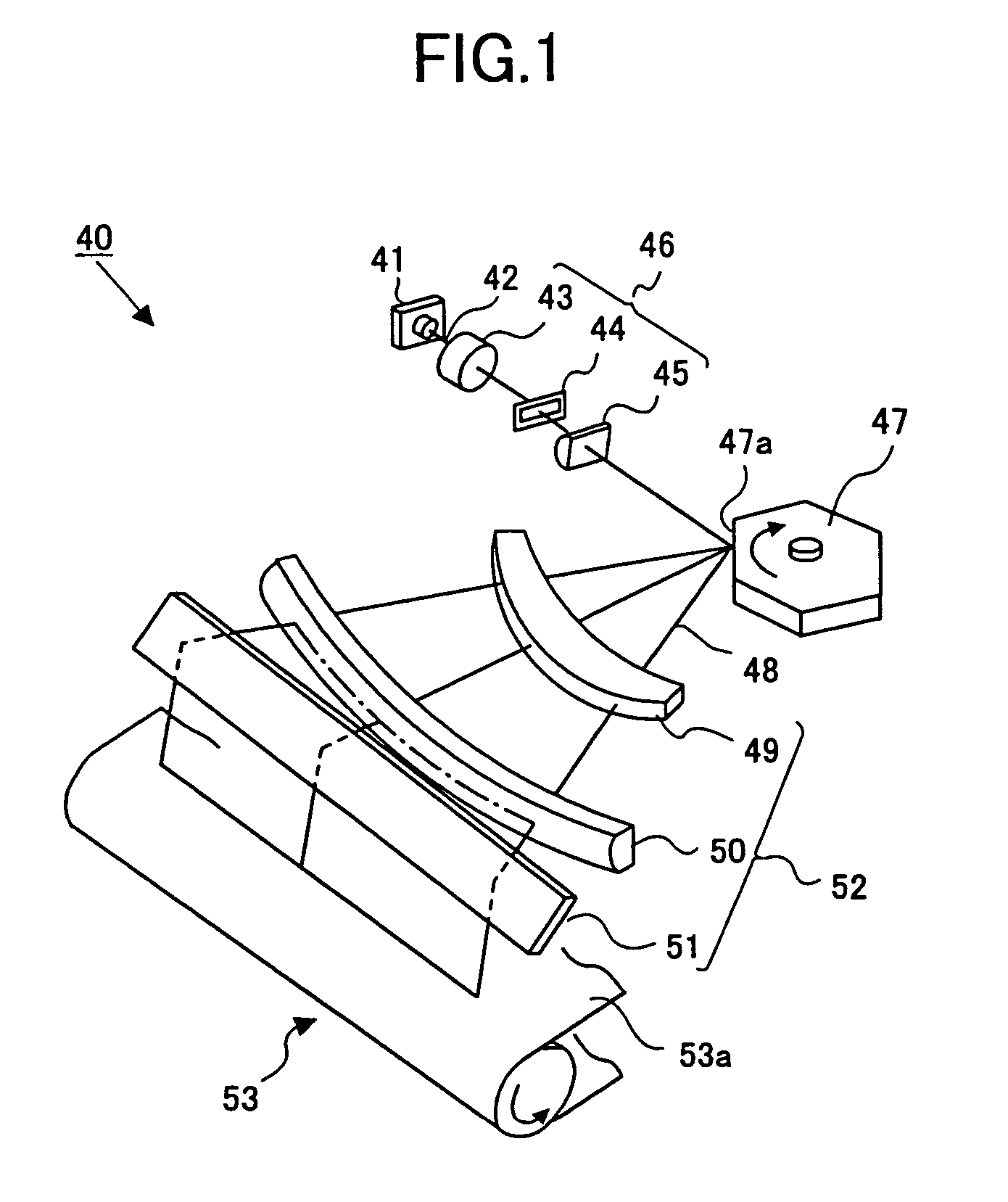
[0045]The optical scanning device 1 directs a light beam (light flux) 3a emitted from a laser light source 2 through a first optical system 7 to a polygon mirror 9 of a polygon scanner 8 which is a mechanical deflector, and causes the light beam to be reflected by a mirror surface 9a, the angle of which changes with rotation of the polygon mirror 9. Thereby, the light beam is deflected in a main scanning direction (the direction of the arrow A shown in FIG. 2A). At the same time, the deflected light 3b is directed through a second optical system 13 to a surface 14a (surface to be scanned) of a photosensitive body drum 14 which rotates in a sub-scanning direction (the direction of the arrow B shown in FIG. 2B). Thereby, o...
second embodiment
[0066]According to the present invention, the material of the housing 20 has the heat conductivity smaller than that of the material of the holding member 23. When the heat conductivity of the housing 20 is smaller than the heat conductivity of the holding member 23 holding the polygon scanner 8 which is a heat source, heat from the polygon scanner 20 is not easily transmitted to the housing 20. Accordingly, it is possible to effectively prevent the other respective optical components from being heated. As a result, it is possible to prevent performance of the optical scanning device 1 from being degraded.
[0067]For example, in a case where aluminum is used as the material of the holding member 23 holding the polygon scanner 8, it is possible that heat generated by the polygon scanner 8 is not easily transmitted to the housing 20 as a result of using iron or steel having the heat conductivity smaller than that of aluminum as the material of the housing 20. The following table shows t...
third embodiment
[0069]According to the present invention, as shown in FIGS. 5A and 5B, the polygon scanner 8 is directly mounted to the housing body 20A, and, also, the material of the housing 20 is made to be one having the heat conductivity smaller than those of the materials of contacting parts, that is, the motor case 16a and a mounting plate 8a.
[0070]Accordingly, in a case where the polygon scanner 8 is directly mounted to the housing body 20A, heat from the polygon scanner 8 is not easily transmitted to the housing 20 when the heat conductivity of the housing body 20A is smaller than the heat conductivities of the motor case 16a and mounting plate 8a. As a result, it is possible to effectively prevent a rise in temperature of the other respective optical components, and to prevent the performance of the optical scanning device 1 fro; being degraded.
[0071]Thus, by preventing the heat generated by the polygon scanner 8 from being easily transmitted to the housing body 20A, it is possible to pr...
PUM
 Abstract
Description
Claims
Application Information
 - R&D
- Intellectual Property
- Life Sciences
- Materials
- Tech Scout
- Unparalleled Data Quality
- Higher Quality Content
- 60% Fewer Hallucinations
Browse by: Latest US Patents, China's latest patents, Technical Efficacy Thesaurus, Application Domain, Technology Topic, Popular Technical Reports.
© 2025 PatSnap. All rights reserved.Legal|Privacy policy|Modern Slavery Act Transparency Statement|Sitemap|About US| Contact US: help@patsnap.com


