Oscillator device and optical deflector using the same
- Summary
- Abstract
- Description
- Claims
- Application Information
AI Technical Summary
Benefits of technology
Problems solved by technology
Method used
Image
Examples
first embodiment
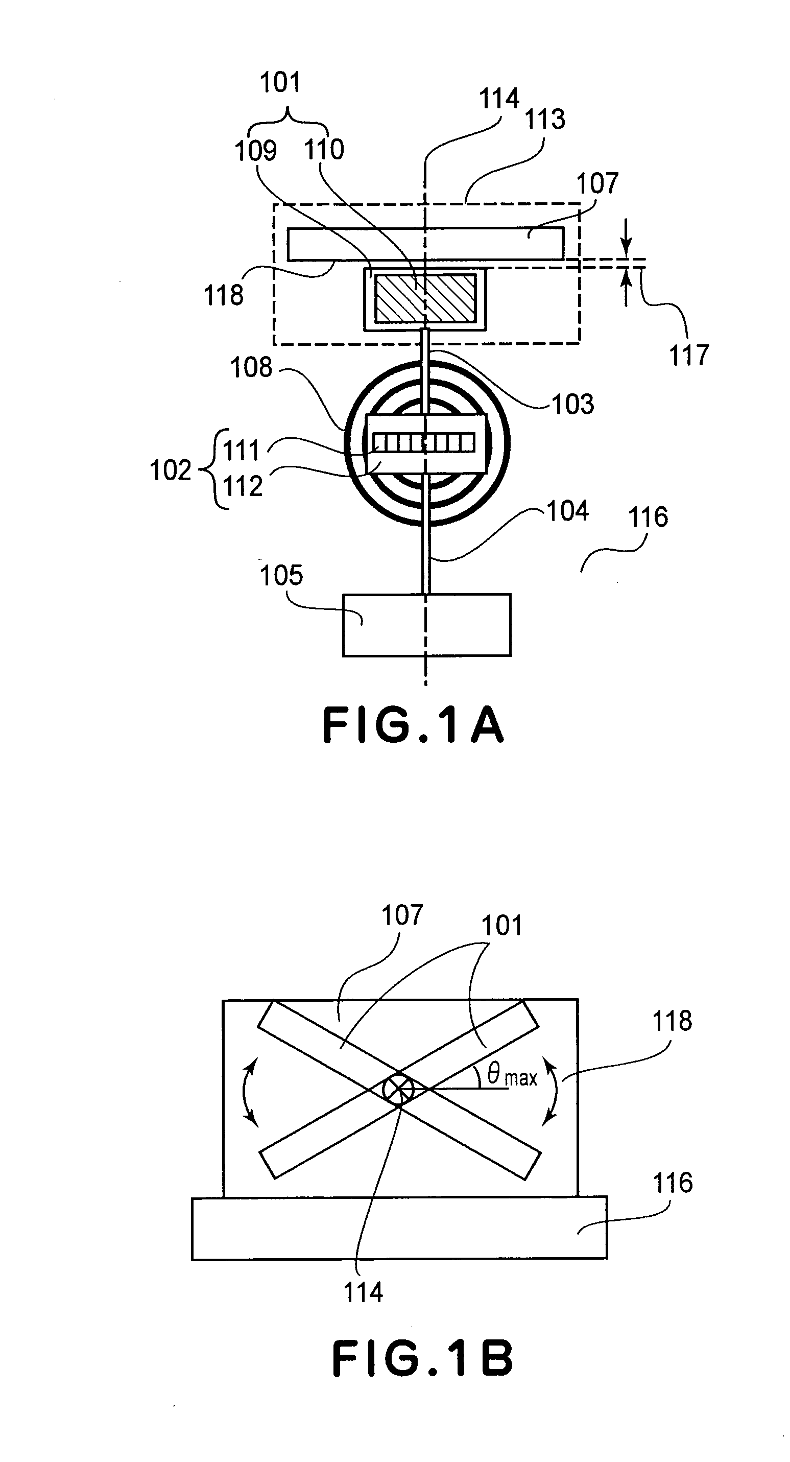
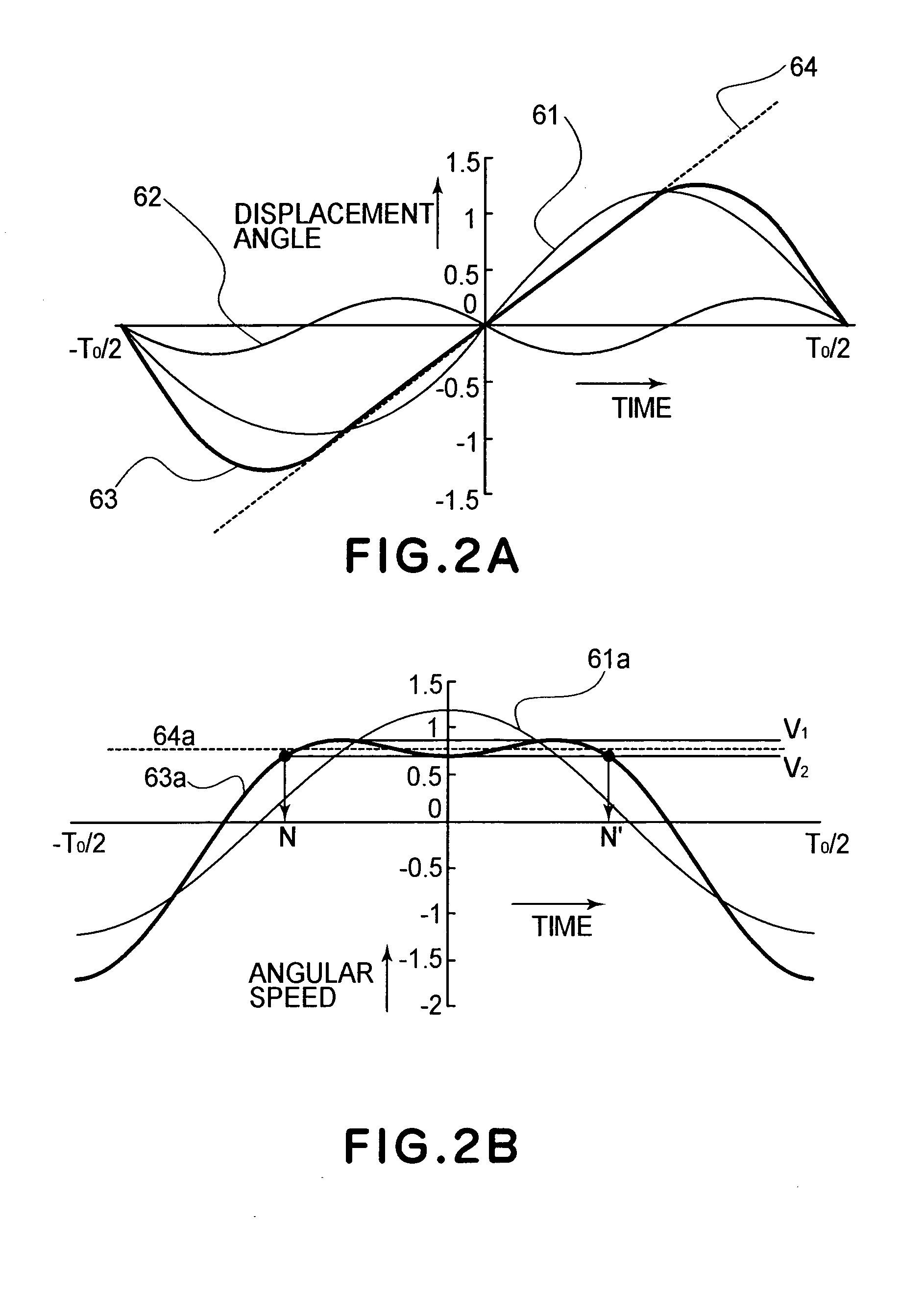
[0039]Referring to FIG. 1 to FIG. 5, an optical deflector according to a first embodiment of the oscillator device of the present invention will be explained. FIG. 1A is a front elevation of the optical deflector of the present embodiment. FIG. 1B is a plane view showing a region 113 in FIG. 1A. As shown in FIGS. 1A and 1B, the optical deflector of the present embodiment comprises a first movable element 101, a second movable element 102, and two types of torsion springs 103 and 104 disposed along a straight line (torsional axis 114) connecting the two movable elements 101 and 102 in series. The first movable element 101 is supported by the first torsion spring 103. The second movable element 102 supports the first torsion spring 103, and it is supported by the second torsion spring 104. A supporting member 105 supports the second torsion spring 104. In this way, the tabular first movable element and second movable element are supported by the torsion springs for torsional oscillati...
second embodiment
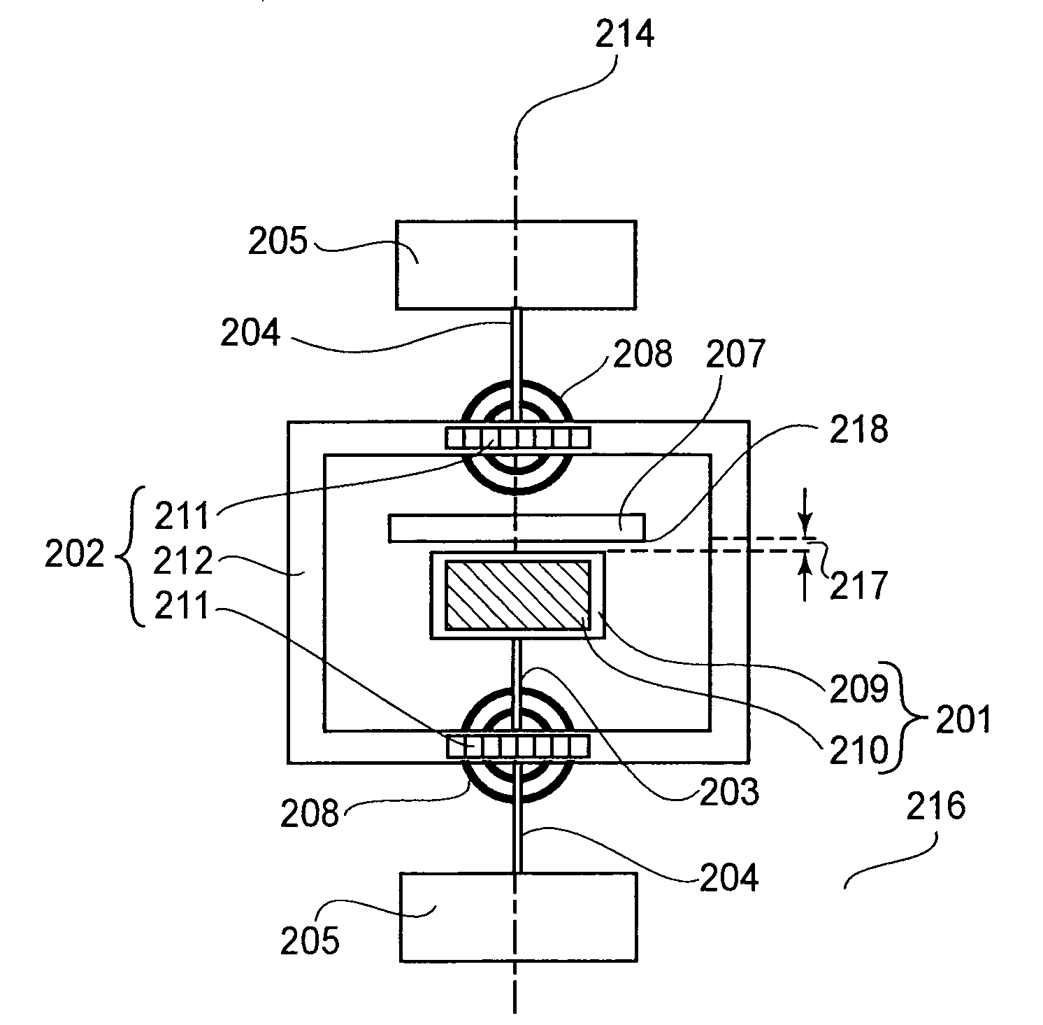
[0066]An optical deflector according to a second embodiment of the oscillator device of the present invention will be explained. FIG. 7A is a front elevation of the optical deflector of the present embodiment. FIG. 7B is a plane view of a region 613 of FIG. 7A. FIG. 7C is a plane view of a region 619 of FIG. 7A. In this embodiment, as shown in FIG. 7A, one movable element 601 is supported by one torsion spring 603, and a supporting member 605 supports the torsion spring 603. A supporting base plate 616 supports the supporting member 605 and two damper members 607.
[0067]The movable element 601 is comprised of a reflection surface 610, a silicon member 609 and a hard magnetic material 611. The material of the reflection surface 610 provided on the top surface of the silicon member 609 is aluminum, for example. It is formed there by vacuum deposition. A protection film may be formed on the topmost surface of the reflection surface 610. The hard magnetic material 611 is a permanent magn...
third embodiment
[0072]An optical deflector according to a third embodiment of the oscillator device of the present invention will be explained. As shown in FIG. 9 which is a front elevation, in the optical deflector of the present embodiment, the shape of the first movable element 1201 is a diamond shape. A damper member 1207 having a damper surface 1218 is provided along a locus plane of conical shape defined by two sides of the rhombus. The damper member 1207 is formed symmetrically about the torsion axis 1214. FIG. 9 is a front elevation for explaining the portion around the first movable element 1201. The remaining points are similar to the optical deflector of FIG. 1. In accordance with the present embodiment, the portion of the reflection surface 1210 which is spaced apart from the torsion axis 1214 reduces, such that the air resistance which the first movable element 1201 receives during the torsional oscillation is reduced. Thus, the oscillation of first movable element 1201 is stabilized f...
PUM
 Abstract
Description
Claims
Application Information
 - R&D
- Intellectual Property
- Life Sciences
- Materials
- Tech Scout
- Unparalleled Data Quality
- Higher Quality Content
- 60% Fewer Hallucinations
Browse by: Latest US Patents, China's latest patents, Technical Efficacy Thesaurus, Application Domain, Technology Topic, Popular Technical Reports.
© 2025 PatSnap. All rights reserved.Legal|Privacy policy|Modern Slavery Act Transparency Statement|Sitemap|About US| Contact US: help@patsnap.com


