
Optical scanning device and image forming apparatus

a scanning device and image forming technology, applied in the field of optical scanning devices and image forming apparatuses, can solve the problems of reducing the accuracy of the apc and the disadvantage of the disclosed method in realizing high-speed image forming

Inactive Publication Date: 2012-03-01
RICOH KK
View PDF3 Cites 13 Cited by
  • Summary
  • Abstract
  • Description
  • Claims
  • Application Information

AI Technical Summary

Benefits of technology

[0013]According to the optical scanning device as one aspect of the invention, a stable optical scanning can be performed.
[0015]According to the image forming apparatus as one aspect of the invention, high-quality images can be formed, since the apparatus is provided with the optical scanning device as one aspect of the invention.

Problems solved by technology

However, the surface emitting laser has a structure not allowing the light emitted backward therefrom.
Therefore, the disclosed method has a disadvantage in realizing the high speed image forming.
Also in the optical scanning device disclosed by Japanese Patent Application Laid-open No. 2007-298563, the proposed method has a disadvantage in a point that the accuracy of the APC decreases, when the splitting device has any machining error.

Method used


Image

  • Optical scanning device and image forming apparatus
  • Optical scanning device and image forming apparatus
  • Optical scanning device and image forming apparatus

Examples


Embodiment Construction

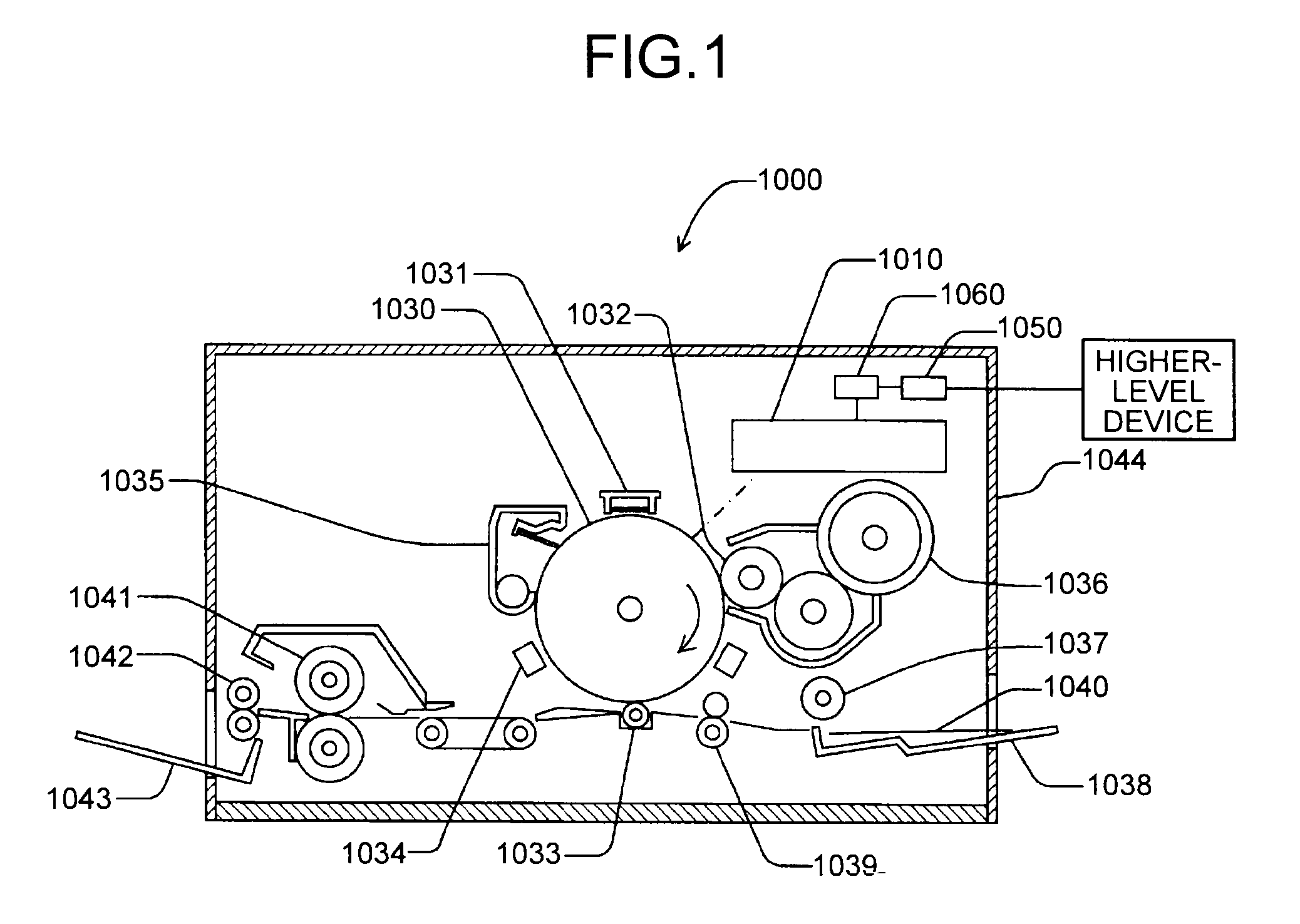
[0035]An embodiment of the present invention is described below with reference to FIGS. 1 to 9. FIG. 1 shows a configuration of a laser printer 1000 according to one embodiment.

[0036]The laser printer 1000 includes an optical scanning device 1010, a photosensitive element 1030, an electrical charger 1031, a developing roller 1032, a transfer charger 1033, a neutralizing unit 1034, a cleaning unit 1035, a toner cartridge 1036, a paper feeding roller 1037, a paper cassette 1038, a pair of registration rollers 1039, a fixing roller 1041, a discharge roller 1042, a discharge tray 1043, a communication control device 1050, and a printer control device 1060 that integrally controls each of the above components and / or devices. The above components and / or devices are disposed in their predetermined positions inside a printer housing 1044.

[0037]The communication control device 1050 controls an interactive communication with a higher-level device (for example, a personal computer) via a netwo...


PUM


Abstract

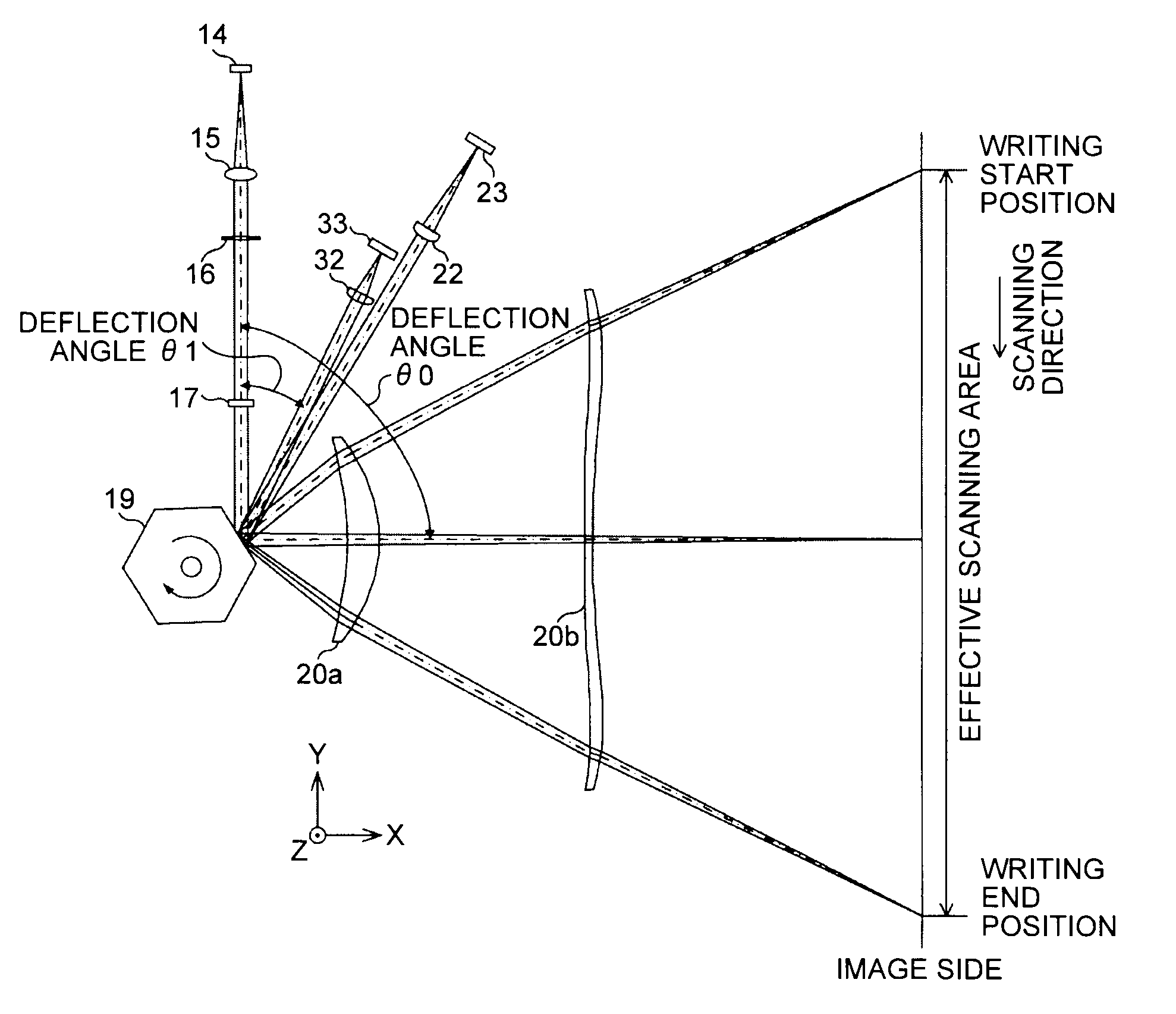
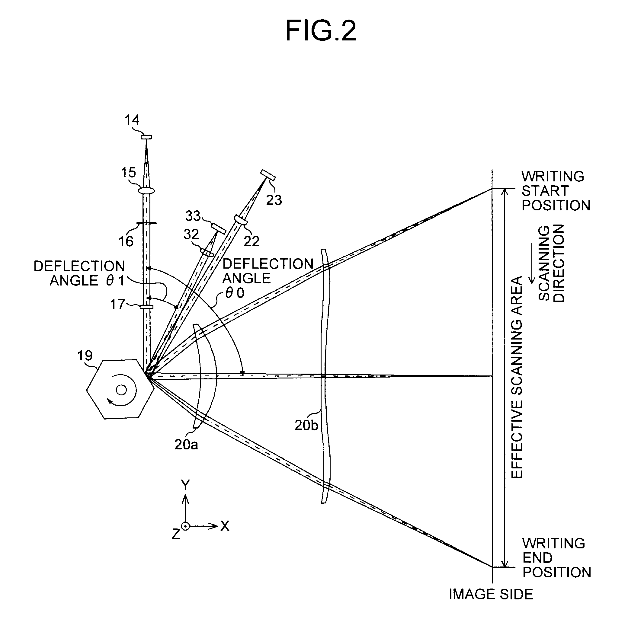
An optical scanning device that scans a scanning surface in a main scanning direction. The device includes a surface emitting laser as a light source, an optical deflector that deflects a light flux from the light source while rotating around a rotation axis, a monitor light receiving element, a synchronization detection light receiving element, a monitor optical system that directs the monitor light flux to the monitor light receiving element, a synchronization detection optical system that directs the synchronization detection light flux to the synchronization detection light receiving element, and a scanning optical system that directs a scanning light flux to the scanning surface. A combined focal length of the monitor optical system in the main scanning direction is smaller than a combined focal length of the synchronization detection optical system in the main scanning direction.

Description

CROSS-REFERENCE TO RELATED APPLICATIONS[0001]The present application claims priority to and incorporates by reference the entire contents of Japanese Patent Application No. 2010-188025 filed in Japan on Aug. 25, 2010.BACKGROUND OF THE INVENTION[0002]1. Field of the Invention[0003]The present invention relates to an optical scanning device and an image forming apparatus and, more particularly, to an optical scanning device that scans a scanning surface with light and an image forming apparatus that includes the optical scanning device.[0004]2. Description of the Related Art[0005]Image forming apparatuses that utilize a laser as a light source are often used for forming electrophotographic images. For that purpose, the image forming apparatus is equipped with an optical scanning device that scans the surface of a photosensitive element with a light flux (a scanning light flux) that has been emitted from the light source and deflected by an optical deflector in order to form a latent i...

Claims


Application Information

Patent Timeline
IPC IPC(8): B41J2/415G02B26/08
CPCB41J2/473G02B27/0031G02B26/127G02B26/125
Inventor SAKAI, KOHJI
Owner RICOH KK
Learn More