Optical scanning apparatus, optical writing apparatus, image forming apparatus, and method of driving vibration mirror
- Summary
- Abstract
- Description
- Claims
- Application Information
AI Technical Summary
Benefits of technology
Problems solved by technology
Method used
Image
Examples
first embodiment
(First Embodiment)
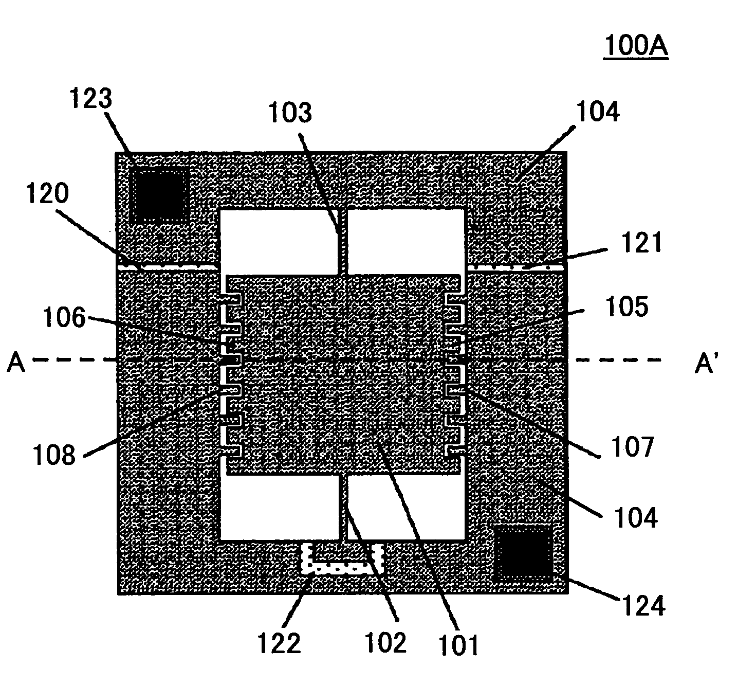
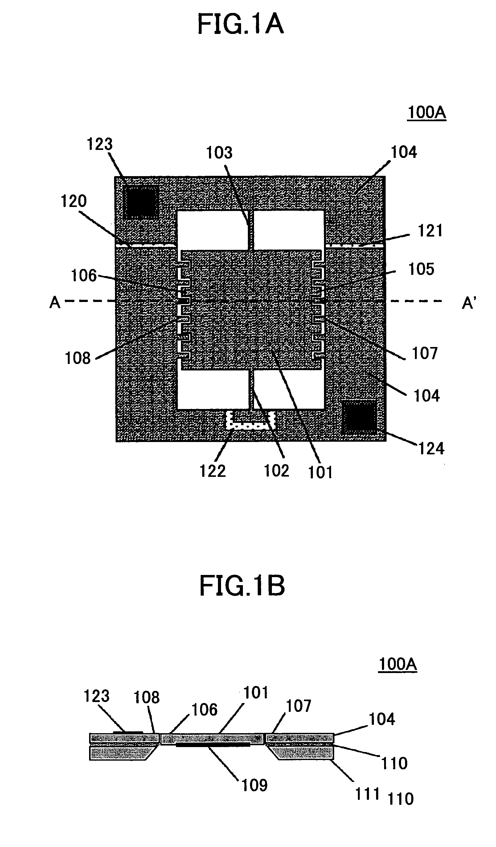
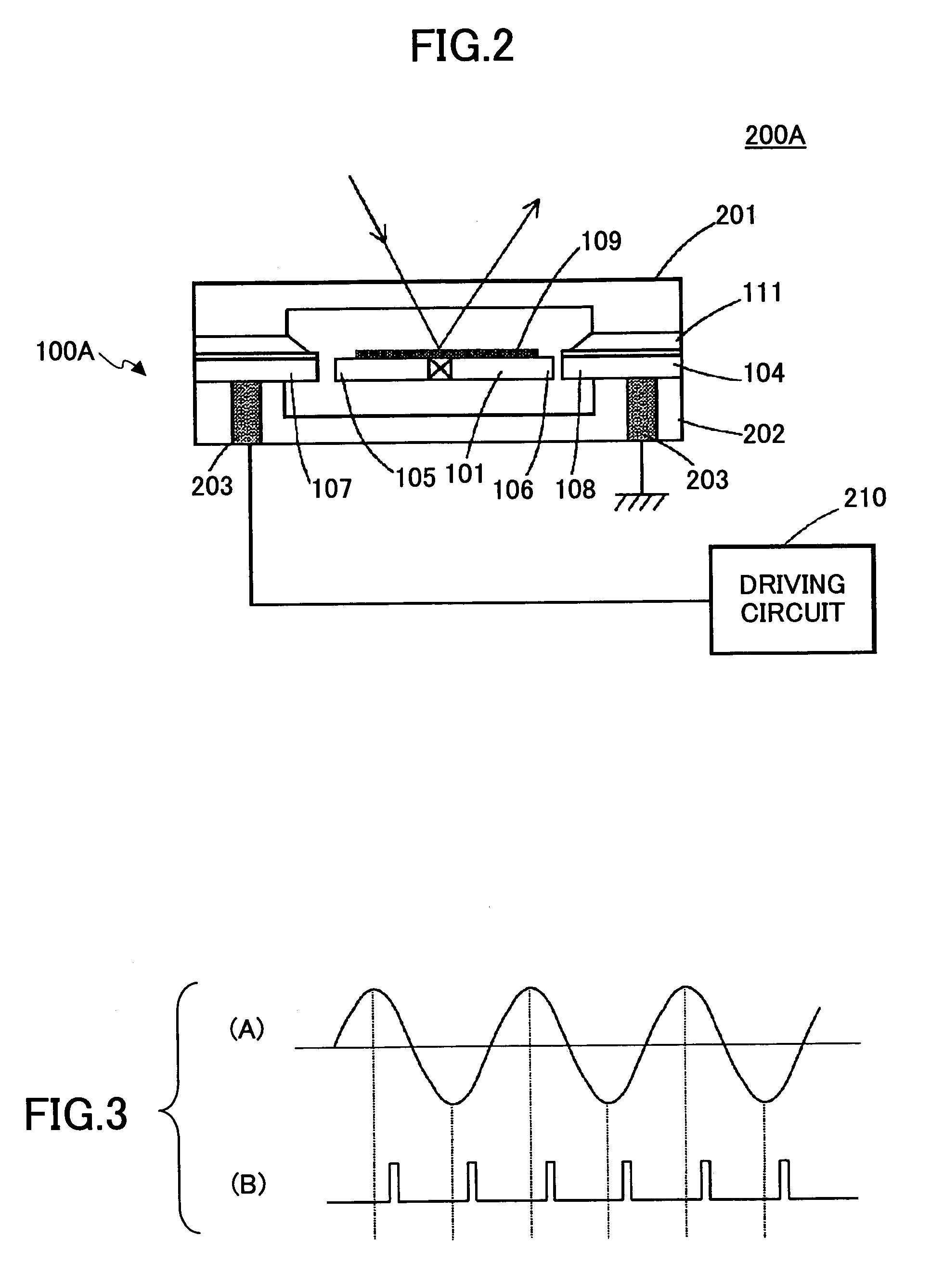
[0219]A description is given below of the first embodiment of the present invention. FIGS. 1A and 1B show the structure of a vibration mirror 100A used in an optical scanning apparatus 200A according to this embodiment. FIG. 2 shows the general structure of the optical scanning apparatus 200A.
[0220]FIG. 1A is a schematic plan view of the vibration mirror 100A seen from the side opposite to a mirror surface of the vibration mirror 10A. FIG. 1B is a schematic cross sectional view of the vibration mirror 100A taken along the line A–A′ in FIG. 1A.
[0221]The vibration mirror 100A shown in FIG. 1A includes a mirror substrate 101, torsion beams 102 and 103, and a frame supporting part 104. The mirror substrate 101 is supported by the frame supporting part 104 via the torsion beams 102 and 103 at the central portions of two opposing ends thereof. The mirror substrate 101 can perform reciprocating vibration while using the torsion beams 102 and 103 as the torsion rotation ax...
second embodiment
(Second Embodiment)
[0231]A description is given below of a second embodiment of the present invention. FIGS. 6A, 6B and 6C show the structure of a vibration mirror 100B used in an optical scanning apparatus 200B according to this embodiment. FIG. 7 shows a general structure of the optical scanning apparatus 200B.
[0232]FIG. 6-(A) is a schematic plan view of the vibration mirror 100B seen from the side opposite to the mirror surface 109. FIG. 6-(B) is a schematic cross-sectional view of the vibration mirror 100B taken along the line A–A′ in FIG. 6-(A). FIG. 6-(C) is a schematic plan view of the vibration mirror 100B seen from the mirror surface 109 side.
[0233]In FIG. 6, those parts that are the same as those corresponding parts in FIG. 1 are designated by the same reference numerals. The vibration mirror 100B of the second embodiment structurally differs from the vibration mirror 100A of the first embodiment in that: second comb-like driving electrodes (driving electrodes) 112 and 113...
third embodiment
(Third Embodiment)
[0242]According to a third embodiment of the present invention, the driving circuit 230 may drive the vibration mirror 100B at a vibration frequency similar to that in the second embodiment by applying the driving pulse as shown in FIG. 10 to each of the electrodes 107, 108, 112 and 113. In FIG. 10, (A) represents the vibration waveform of the mirror substrate 101, (B) represents the waveform of the driving pulse applied to the driving electrodes 107 and 108, (C) represents the waveform of the driving pulse applied to the driving electrode 112, and (D) represents the waveform of the driving pulse applied to the driving electrode 113.
[0243]The driving pulse is applied to the driving electrodes 107 and 108 when the swing angle is equal to or less than θo. When the swing angle exceeds θo, the driving pulse is applied to the driving electrodes 112 and 113. In the third embodiment, however, the driving pulse is applied before and after the extreme value of the vibration...
PUM
 Abstract
Description
Claims
Application Information
 - R&D
- Intellectual Property
- Life Sciences
- Materials
- Tech Scout
- Unparalleled Data Quality
- Higher Quality Content
- 60% Fewer Hallucinations
Browse by: Latest US Patents, China's latest patents, Technical Efficacy Thesaurus, Application Domain, Technology Topic, Popular Technical Reports.
© 2025 PatSnap. All rights reserved.Legal|Privacy policy|Modern Slavery Act Transparency Statement|Sitemap|About US| Contact US: help@patsnap.com


