

Container for chemical precursors in a deposition process
- Summary
- Abstract
- Description
- Claims
- Application Information
AI Technical Summary
Benefits of technology
Problems solved by technology
Method used
Image

Examples
working examples
Example 1
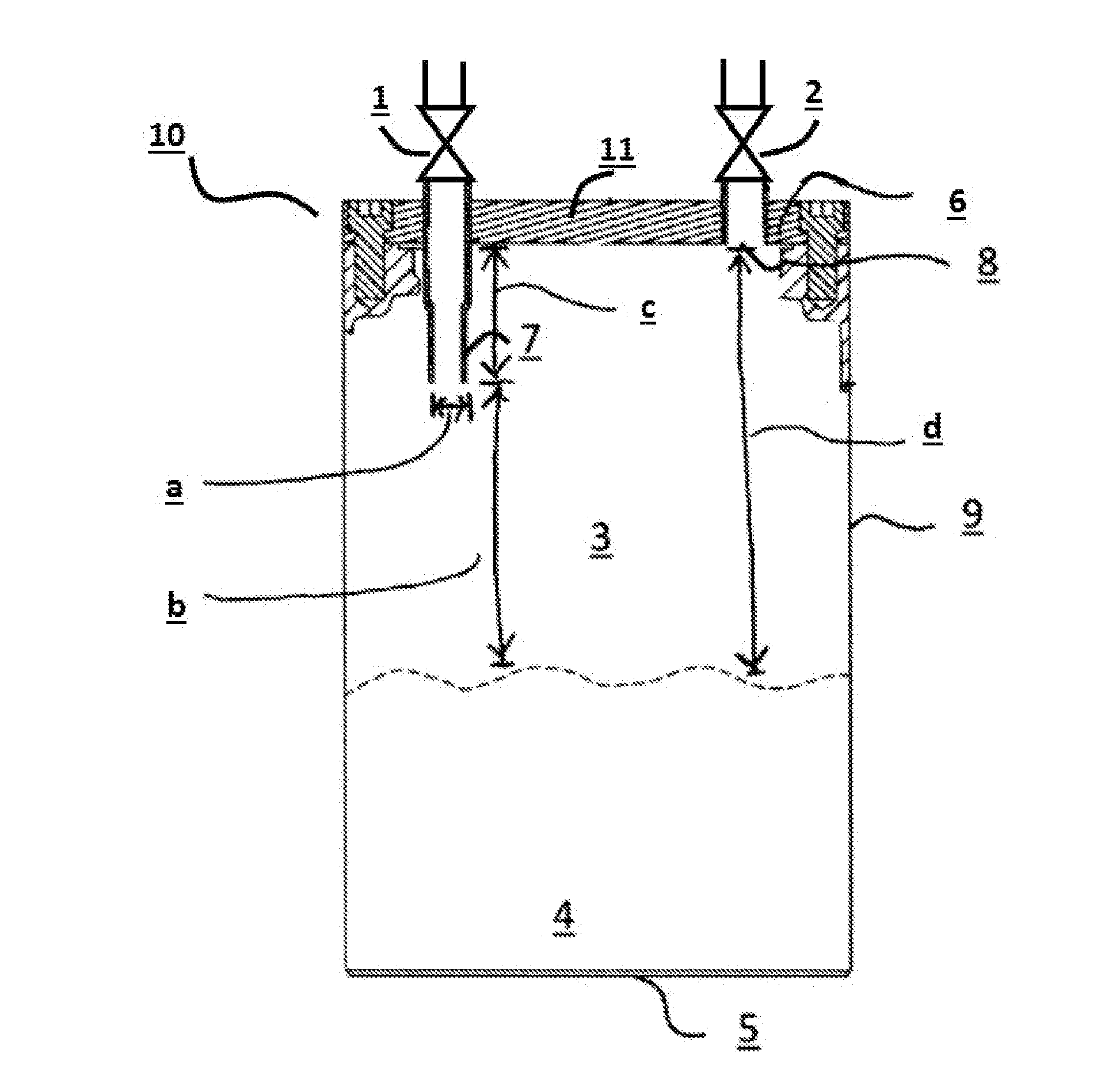
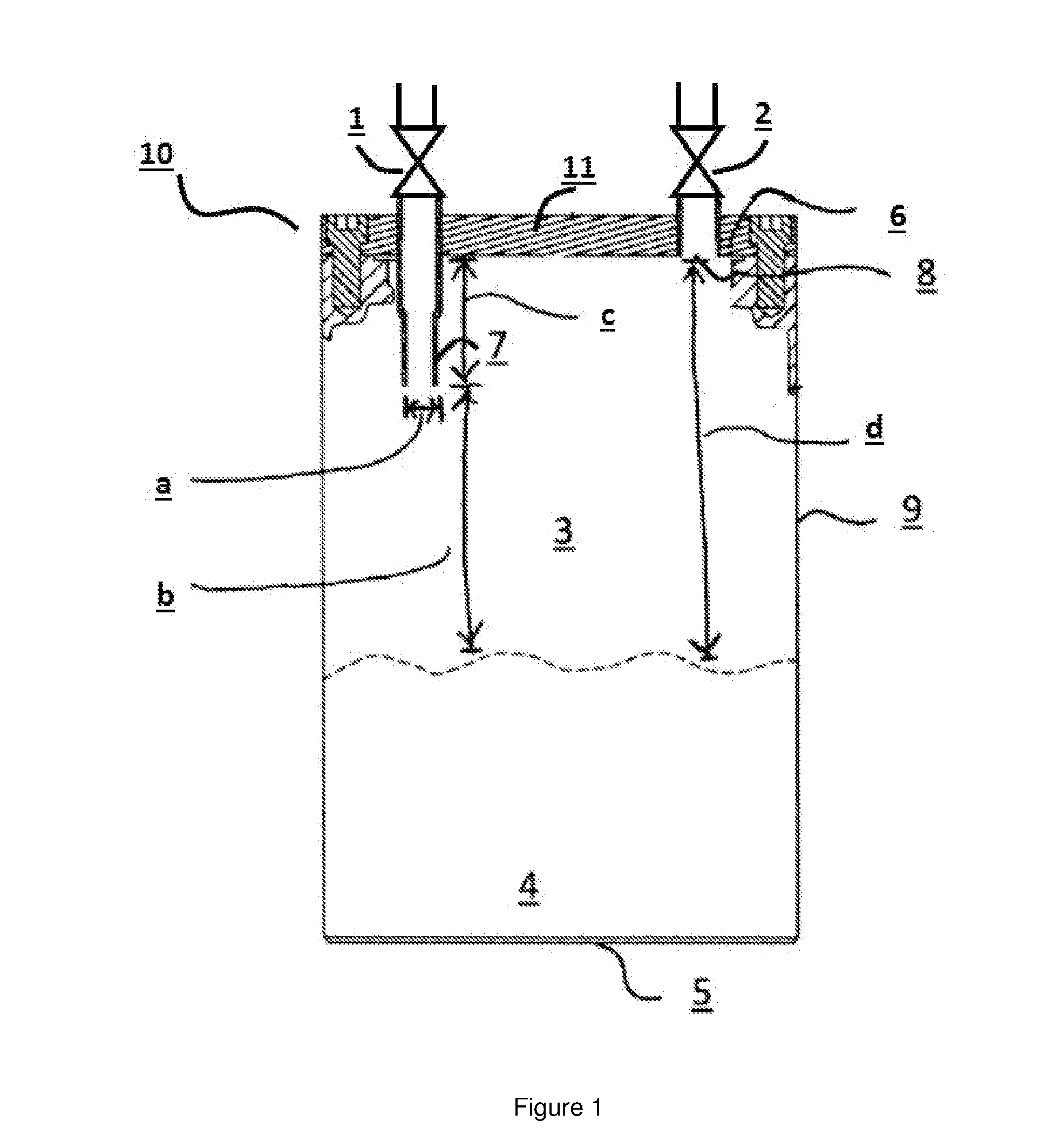
[0123]A 137.4 cubic inch (about 2.24 liters) container having a design depicted in FIG. 1 has been tested in the following manner.
[0124]Firstly, the container was configured with a bubbler-style inlet. More specifically, a 0.5 inch diameter tube submerged to within 0.25 inches from the bottom of the container was used as a bubbler, similar to designs suggested in U.S. Pat. No. 8,313,804 B2 and / or U.S. Pat. No. 6,033,479 A. A glass wool filter element was placed in the outlet tubing to collect any solid particles that might be entrained in the vapor flow exiting the container.
[0125]The container was filled with dicobalt hexacarbonyl tert-butylacetylene, a liquid precursor material with low vapor pressure that contained 12.5 wt % of combined solid and dissolved non-volatile impurities. A carrier gas consisting of nitrogen was delivered into the container at a flow rate of 600 sccm. The temperature and pressure conditions within the container were 50 Torr and room temperature ...
example 2
[0128]The ability of the jet inlet design to achieve high degree of saturation was evaluated.
[0129]For all tests, the liquid chemical being delivered was a solution comprised of 90 weight percent (wt. %) ethylene glycol and 10 wt. % water with a vapor pressure of approximately 5 Torr to simulate a liquid chemical precursor. A carrier gas consisting of nitrogen was delivered into the container at a flow rate of 600 sccm. The temperature and pressure conditions within the container were 50 Torr and room temperature (e.g., about 20-23° C.), respectively.
[0130]For each measurement for the jet inlet design, the inlet configuration of the nozzle was varied to demonstrate the effect of the nozzle cross section width and distance of the nozzle tip to the surface of the liquid chemical (see “b” in FIG. 1). The results are provided in Table 1.
[0131]A comparative prior art configuration or bubbler configuration wherein the carrier gas was injected below the surface of the liquid chemical was a...
example 3
[0143]Using the same containers and same materials under the same process conditions as in Example 1, an ultraviolet-visible spectroscopy cell was placed downstream of the filter element to measure the relative concentration of the precursor in the vapor stream. The relative concentration of the dicobalt hexacarbonyl tert-butylacetylene precursor was determined by comparing the absorbance spectra of the vapor stream when using the bubbler design to that when using the jet inlet design. The magnitude of the absorbance is proportional to the concentration of the precursor under these conditions. The nitrogen carrier gas does not absorb the measured wavelengths of light, so only the precursor is detected.
[0144]Nitrogen carrier gas was flowed through the container at 760, 260 and 100 Torr absolute pressure inside the container.
TABLE 2Relative AbsorbancePressure(Arbitrary Units)(Torr)BubblerJet Inlet7600.0620.0642500.070.0851000.0880.086
[0145]The relative absorbance measured for each pre...
PUM
| Property | Measurement | Unit |
|---|---|---|
| Length | aaaaa | aaaaa |
| Angle | aaaaa | aaaaa |
| Flow rate | aaaaa | aaaaa |
Abstract
Description
Claims
Application Information