Propulsive tail propeller assembly or tail duct fan assembly with cyclic and collective control and/or a method of thrust vectoring for aircraft maneuvering and for helicoptor single rotor head anti torque

Inactive Publication Date: 2015-09-03
REILLY NOLAN JOSEPH
View PDF4 Cites 20 Cited by
  • Summary
  • Abstract
  • Description
  • Claims
  • Application Information

AI Technical Summary

Benefits of technology

[0005]The present invention provides in one embodiment, an aircraft propulsion and control system which generates cyclic and collective pitch with rigidly mounted propeller/fan blades for aircraft maneuvering and helicopter anti-torque and thereby eliminating the problems associated with low speed rudder or elevator control, main rotor control and helicopter tail rotor control. With

Problems solved by technology

Current rotorcraft are limited by speed, maneuverability, altitude or lift efficiency.
Helicopters have a high lift efficiency because of their large disc area which results in a low disc loading but are limited in speed, maneuverability, altitude and range.
These problems are caused by dissymmetry of lift, the high angle of nose pitch, drag from the rotor disc and the low percentage of lift produced from the inner span of the rotor blades.
Tilt rotors have a lower lift efficiency because the disc area is divided into two smaller disc's which results in higher disc loading.
This requires more power to achieve the same amount of lifting force as a rotorcraft wit

Method used


Image

  • Propulsive tail propeller assembly or tail duct fan assembly with cyclic and collective control and/or a method of thrust vectoring for aircraft maneuvering and for helicoptor single rotor head anti torque
  • Propulsive tail propeller assembly or tail duct fan assembly with cyclic and collective control and/or a method of thrust vectoring for aircraft maneuvering and for helicoptor single rotor head anti torque
  • Propulsive tail propeller assembly or tail duct fan assembly with cyclic and collective control and/or a method of thrust vectoring for aircraft maneuvering and for helicoptor single rotor head anti torque

Examples


Example

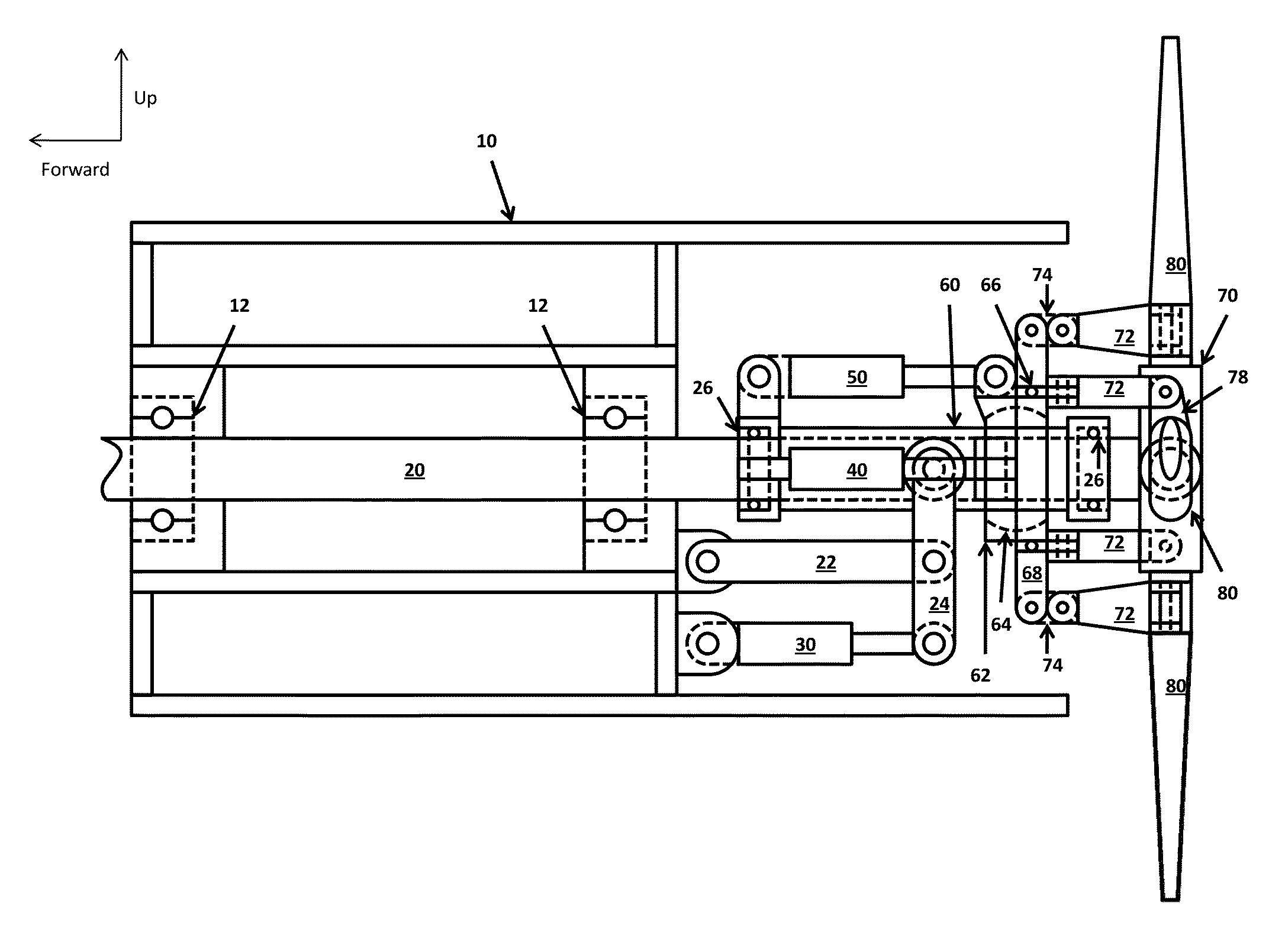
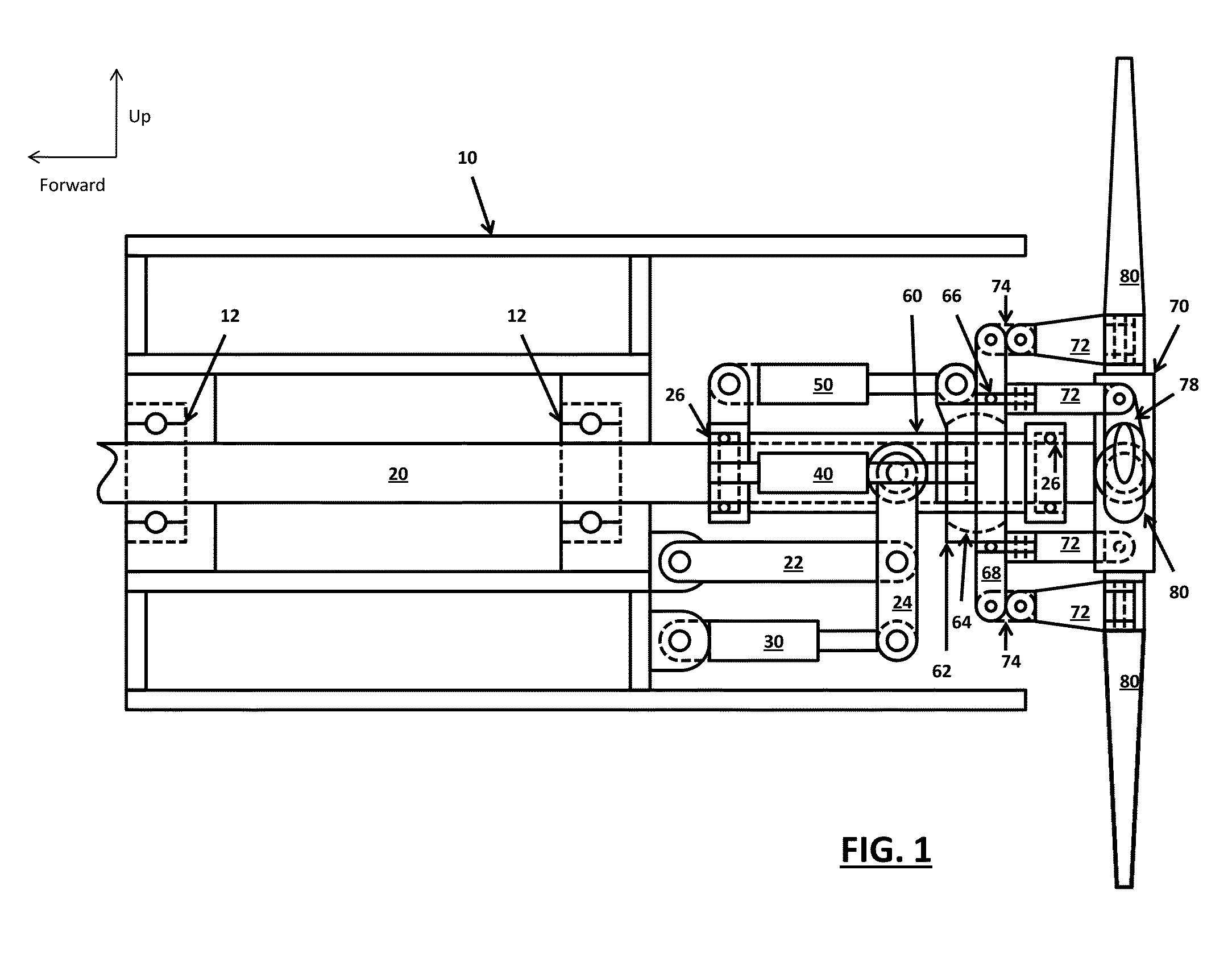
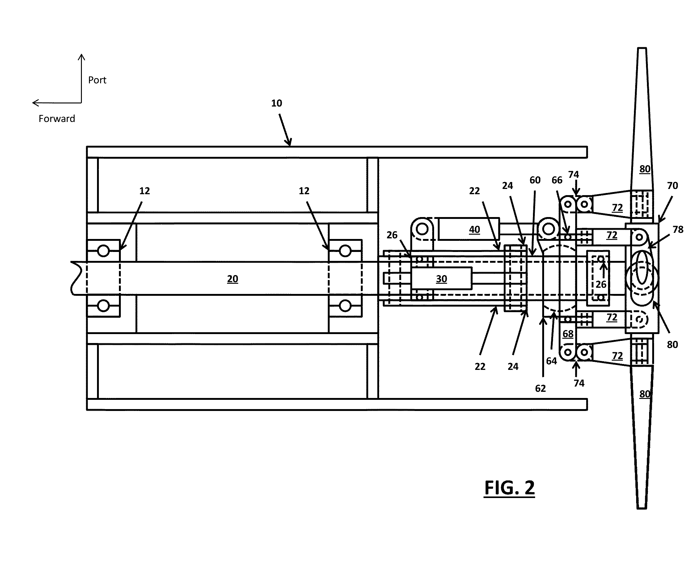
[0043]The propulsive tail propeller / fan assembly 10 maneuvering control system depicted by this embodiment can produce all of the forward, neutral and aft thrust required to accelerate, continuously propel and decelerate an aircraft in a forward or reverse flight direction. The system can also provide the aircraft directional control including pitch, yaw and helicopter single rotor head anti-torque. This is dependent on the drive shaft 20 horse power, propeller / fan blade 80 length, the plurality of the propeller / fan blade 80, rotational speed of the drive shaft 20, propeller / fan blade 80 airfoil and the collective or cyclic propeller / fan blade 80 pitch. The drive shaft 20 is mounted within the drive shaft bearing 12 at two locations along the drive shaft 20 which are supported by the tail assembly 10 airframe structure. The drive shaft bearing 12 allows free rotation of the drive shaft and acts to support it from bending. The large diameter of the drive shaft 20 that transverses the...


PUM


Abstract

A method of aircraft propulsion and control more specific to rotorcraft propulsion and control using forward, neutral and aft thrust in addition to forward/aft thrust coupling from the propulsive tail assembly through cyclic and collective pitch of the non-flapping, ridged propeller/fan blades and/or from a turbojet/turbofan vectored thrust system. The cyclic blade pitch induces a drive shaft bending moment that is used to provide aircraft directional control and also provides anti-torque control for a single rotor head helicopter. The forward/reverse collective thrust actuator, phase lag elevator effect cyclic actuator and phase lag rudder/anti-torque effect cyclic actuator do not require complex control mixing. The vectored thrust system also provides aircraft directional control and anti-torque control individually or combined with the propeller/fan assembly. This assembly eliminates the requirement of rudder or elevator control on a fixed wing aircraft and the requirement of a tail rotor on a conventional helicopter while increasing speed and maneuverability. A slowed or stopped ridged X-wing rotorcraft hub with a modified circular arc airfoil would not require cyclic/collective control.

Description

BACKGROUND OF THE INVENTION[0001]The present invention relates to an aircraft propulsion and control system, and more specific to a rotorcraft propulsion and control system for propeller / fan blade pitch control that induces a drive shaft bending moment and / or a turbojet / turbofan vectored thrust system that is used to provide aircraft directional control and also provides anti-torque control. This system also provides all of the forward, neutral and aft thrust required for a rotorcraft to rapidly accelerate to full speed after transitioning from hover and then to rapidly decelerate back to hover from a forward or reverse flight direction.[0002]Current rotorcraft are limited by speed, maneuverability, altitude or lift efficiency. Helicopters have a high lift efficiency because of their large disc area which results in a low disc loading but are limited in speed, maneuverability, altitude and range. These problems are caused by dissymmetry of lift, the high angle of nose pitch, drag fr...

Claims


Application Information

Patent Timeline
IPC IPC(8): B64C27/605B64C11/32
CPCB64C11/32B64C27/605B64C15/02B64C27/24B64C27/82B64C2027/8236B64C2027/8245
Inventor REILLY, NOLAN JOSEPH
Owner REILLY NOLAN JOSEPH
Why Eureka
Try Eureka