
Tribological debris analysis system

a technology of tribological debris and analysis system, which is applied in the field of fluid inspection systems, can solve the problems of false readings, increase in the amount and size of particulates, and small particulate matter of 50 microns or less in size,

Inactive Publication Date: 2006-03-28
LOCKHEED MARTIN CORP
View PDF27 Cites 58 Cited by
  • Summary
  • Abstract
  • Description
  • Claims
  • Application Information

AI Technical Summary

Problems solved by technology

The early stages of engine wear cause small particulate matter, of about 50 microns or less in size, to be generated.
As the wear process progresses, the amount and size of particulates increase.
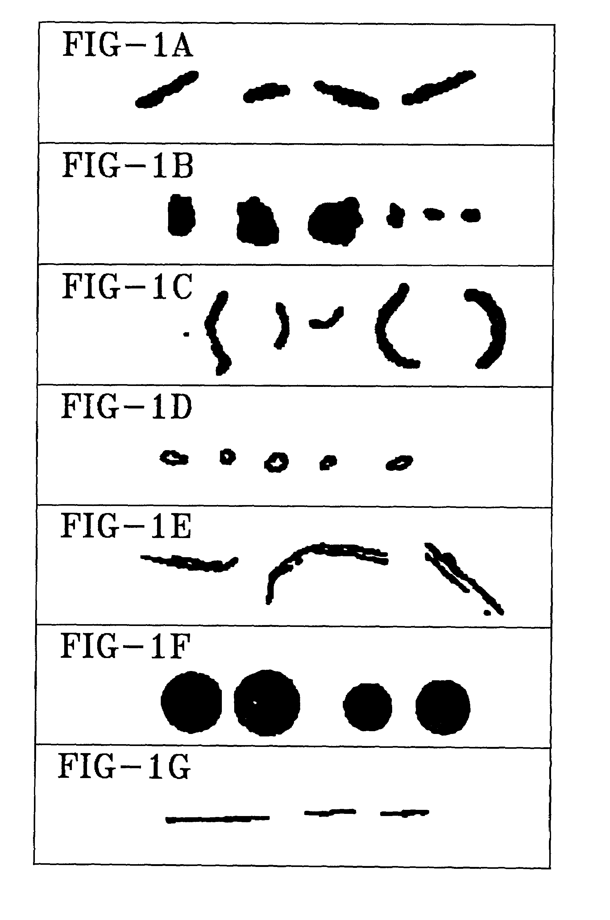
In particular, fibers can be from mishandling the fluid which generate false readings.
But, valid readings of fibers may be indicative of problems in the system.
Finally, FIG. 1G shows flow lines which are a result of instrument problems caused by insufficient replacement of a new sample.
It has been found that the known system is quite expensive and easily overloaded.
Since the computer system is a dedicated device, it is limited in its ability to analyze the particles and detect any trends associated with the particles.
Moreover, the known computer system is unable to check the lifetime history of a particular device when periodic samples are taken from the device.
Therefore, such prior art systems, although effective, are not easily adapted for large scale use and implementation.

Method used


Image

  • Tribological debris analysis system
  • Tribological debris analysis system
  • Tribological debris analysis system

Examples


Embodiment Construction

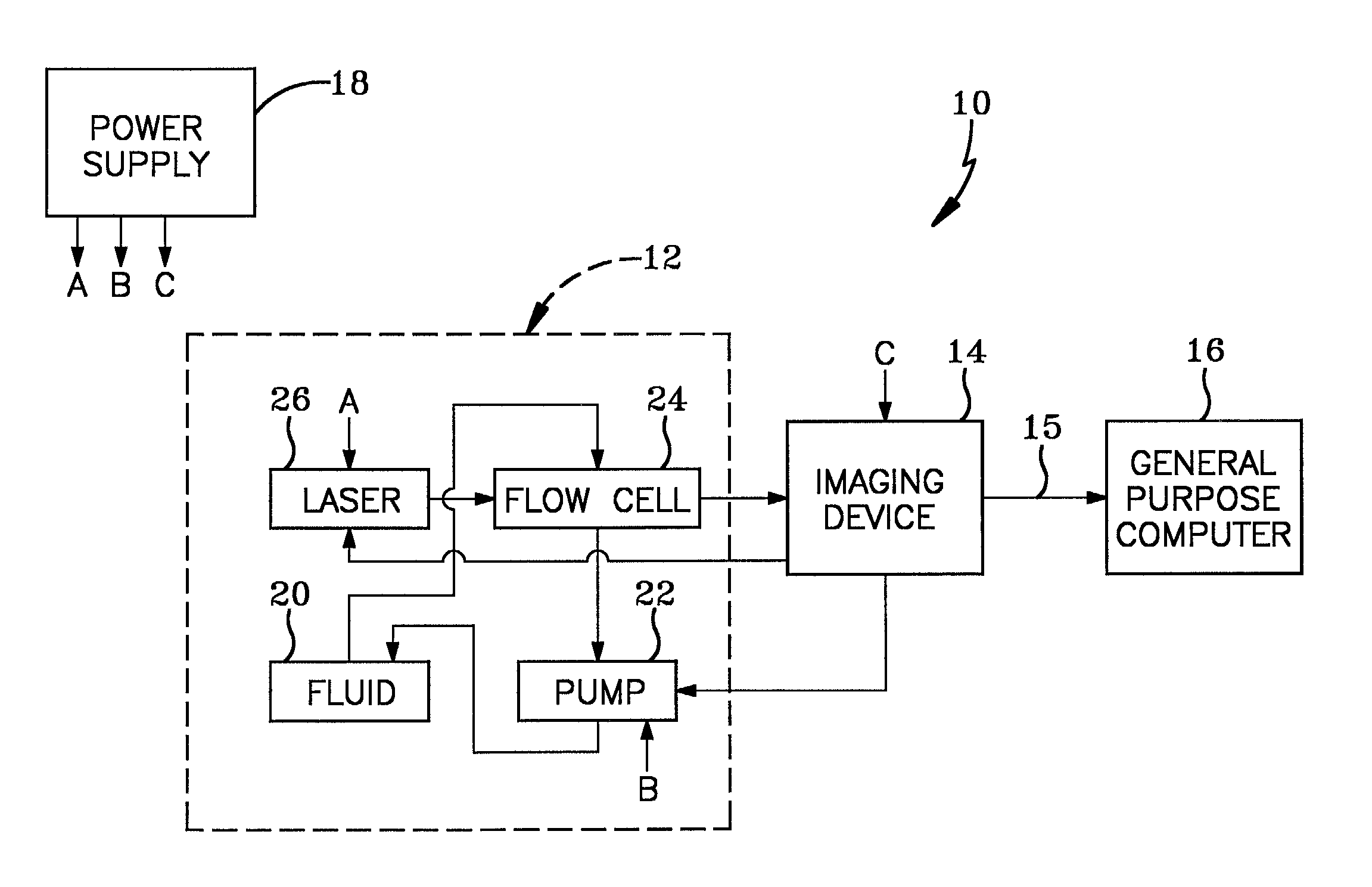
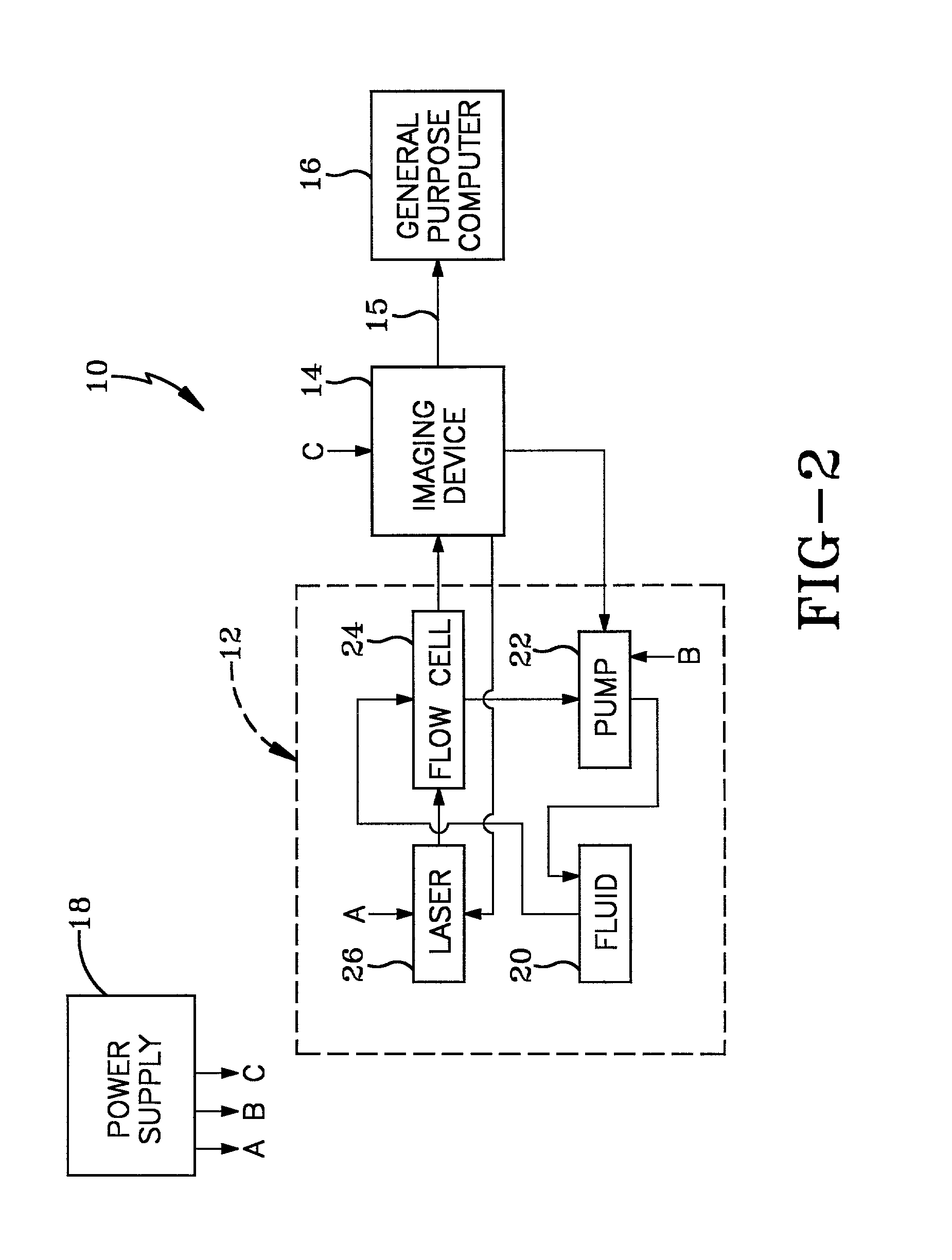
[0020]Referring now to the drawings and, more particularly to FIG. 2, a tribological debris analysis system according to the present invention is designated generally by the numeral 10. The system 10 includes an illumination delivery system 12 and an imaging device 14 which generates a data signal 15 received by a general purpose computer 16. A power supply 18 supplies power to the particular components of the system 10. Although a general purpose computer 16 may be used in the preferred embodiment it will be appreciated that most any computing device with the necessary memory, hardware and software could be utilized in the system 10. In all likelihood, the general purpose computer 16 is powered separately.

[0021]The illumination delivery system 12 includes a fluid container 20 for holding the fluid material to be analyzed. The fluid may be a lubricating oil used in engines and rotating machinery; hydraulic fluid used in various machinery; and fluids used in industrial quality contro...


PUM


Abstract

A tribological debris analysis system includes a general purpose computer; and a tribological sensor system for generating data. The sensor system includes an optical flow cell a pump for pumping a fluid through the optical flow cell, a laser for illuminating the fluid flowing through the optical flow cell, and an imaging device for detecting any debris in the fluid illuminated by the laser. The imaging device sends the object information—in either the form of object elements or objection segments—representative of the debris to the general purpose computer for analysis. The general purpose computer classifies the debris according to size, any trends associated with the size of the debris, generating shape features of the imaged debris and identifying a type of object wear based upon the shape features.

Description

TECHNICAL FIELD[0001]The present invention relates generally to fluid inspection systems. More particularly, the invention relates to a system to ensure accurate imaging of debris viewed through an optical flow cell. Specifically, the invention relates to a system that controls various components in the system and the exchange of data between those components.BACKGROUND ART[0002]It is known to provide fluid sampling devices using optical near-field imaging as disclosed in U.S. Pat. No. 5,572,320, which is incorporated herein by reference. Such a device is employed to determine the quantity, size, characteristics, and types of particulate matter in fluids. Examples of fluids which are monitored in such a system are lubricating oils used in engines and rotating machinery; hydraulic fluid used in various machinery; and fluids used in industrial quality control, food processing, medical analysis, and environment control. In its most common use, such a device monitors engine oil for meta...

Claims


Application Information

Patent Timeline
IPC IPC(8): G01N15/02G06K9/62G01N15/14
CPCG01N15/147G01N2015/1497G01N2015/1493
Inventor SEBOK, THOMAS J.SEBOK, DALE R.KOLP, JOSEPH P.
Owner LOCKHEED MARTIN CORP
Learn More