
Sheet supplying apparatus and image reading apparatus comprising the same

a technology of image reading apparatus and supplying apparatus, which is applied in the direction of electrographic process apparatus, thin material processing, instruments, etc., can solve the problems of increasing the size of the apparatus, slipping sheets, and difficulty in smooth transport of sheets, so as to prevent image blur

Active Publication Date: 2006-03-28
NISCA KK
View PDF15 Cites 15 Cited by
  • Summary
  • Abstract
  • Description
  • Claims
  • Application Information

AI Technical Summary

Benefits of technology

[0014]A sheet is conveyed from the sheet feeding stacker to the processing platen while being pulled by a conveying roller at an upstream side. The sheet is smoothly and accurately conveyed by the idle rollers located inside the U-shape conveying path. After passing through the processing platen, the sheet is guided to the sheet discharging roller by the idle roller located outside the U-shape conveying path, thereby significantly reducing conveyance load.
[0035]According to the present invention, an image reading apparatus includes a U-shape conveying path for guiding a sheet from a sheet feeding stacker to a sheet discharging stacker arranged in parallel in a vertical direction; photoelectric converting means for reading an image on the sheet on a processing platen; separating means for separating the sheet on the sheet feeding stacker; register means for temporarily stopping the sheet from the separating means and conveying the sheet toward a downstream side; a sheet feeding roller for conveying the sheet from the register means to the processing platen; a sheet conveying roller for conveying the sheet from the processing platen toward a downstream side; and sheet discharging means for discharging the sheet from the sheet conveying means to the sheet discharging stacker. The sheet feeding roller is composed of two or more rollers spaced in a direction orthogonal to a sheet conveying direction. Idle rollers operating idly in contact with the sheet are placed between the rollers so that an outer periphery of each idle roller crosses an outer periphery of the corresponding roller in the sheet conveying direction, so that the sheet is guided to the processing platen using the outer periphery of the sheet feeding roller and the outer periphery of the idle roller. Accordingly, it is possible to prevent image blur at leading and trailing ends of the sheet in the image reading apparatus.

Problems solved by technology

Further, the sheet slipped while moving to a processing platen.
The problem may be caused by friction between the sheet and a transport path extending from the sheet feeding stacker to the sheet discharging stacker.
To solve this problem, it is necessary to use a driving motor with high driving power, thereby increasing the size of the apparatus.
However, even if such an idle roller is disposed at a substantially central portion of the U-shaped path for reducing friction, when a distance between a sheet feeding stacker and a discharging stacker is reduced, a sheet receives a large resistance at an outlet of the sheet feeding stacker and an inlet of the sheet discharging stacker, thereby making it difficult to transport the sheet smoothly.
Accordingly, even if the idle roller is disposed at a substantially central portion of the U-shaped path, it is difficult to reduce the friction.
As a result, with the conventional structures disclosed in the patent references described above, it is difficult to accurately feed a wide range of sheets from thin paper to cardboard.
It is also difficult to effectively reduce the size and weight of the apparatus.
Further, in the conventional structures described above, it is difficult to prevent disturbance of a sheet when a leading end thereof enters the processing platen and prevent flip-up of a sheet when a trailing end of the sheet moves away from a sheet feeding roller.

Method used


Image

  • Sheet supplying apparatus and image reading apparatus comprising the same
  • Sheet supplying apparatus and image reading apparatus comprising the same
  • Sheet supplying apparatus and image reading apparatus comprising the same

Examples


Embodiment Construction

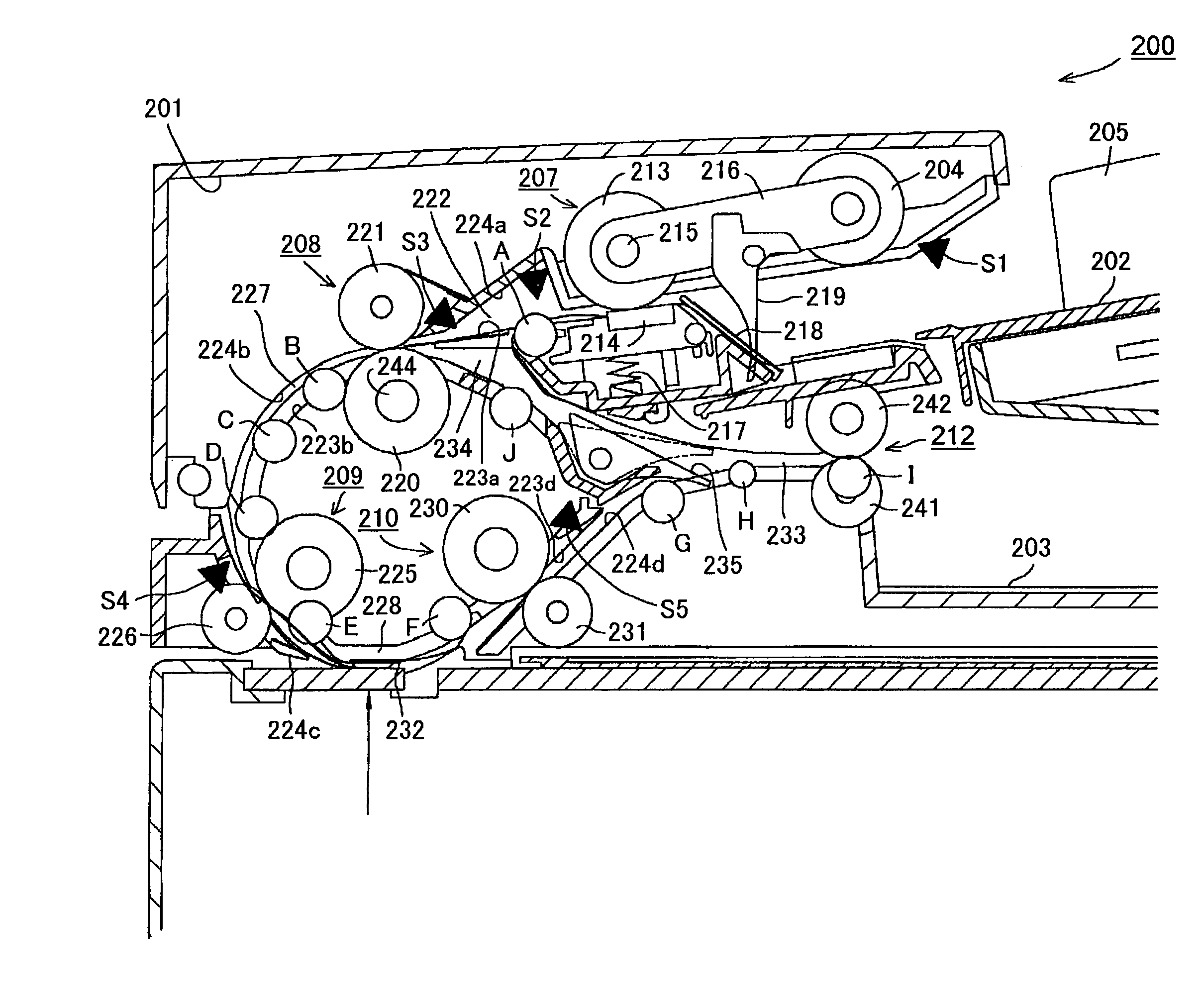
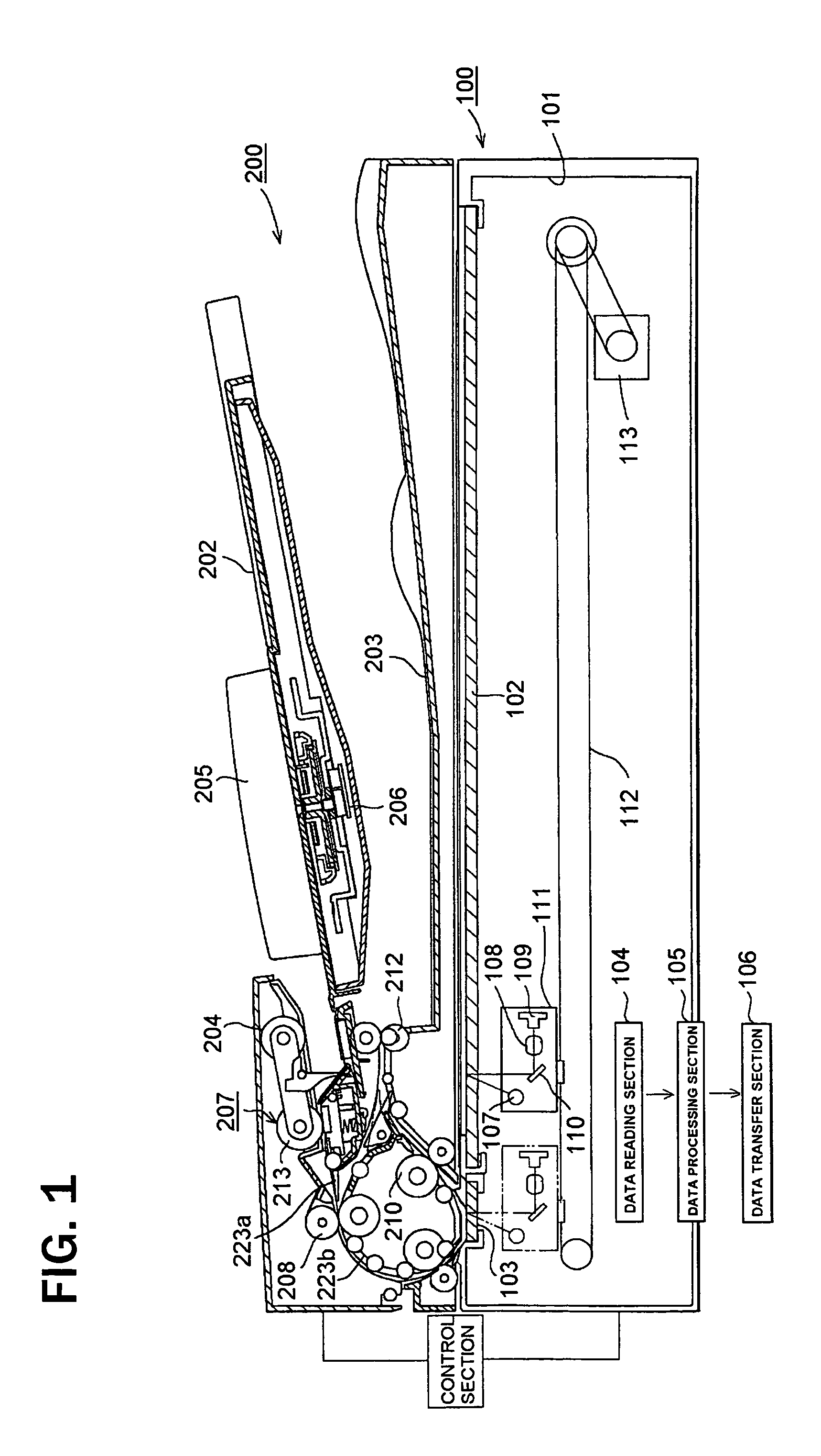
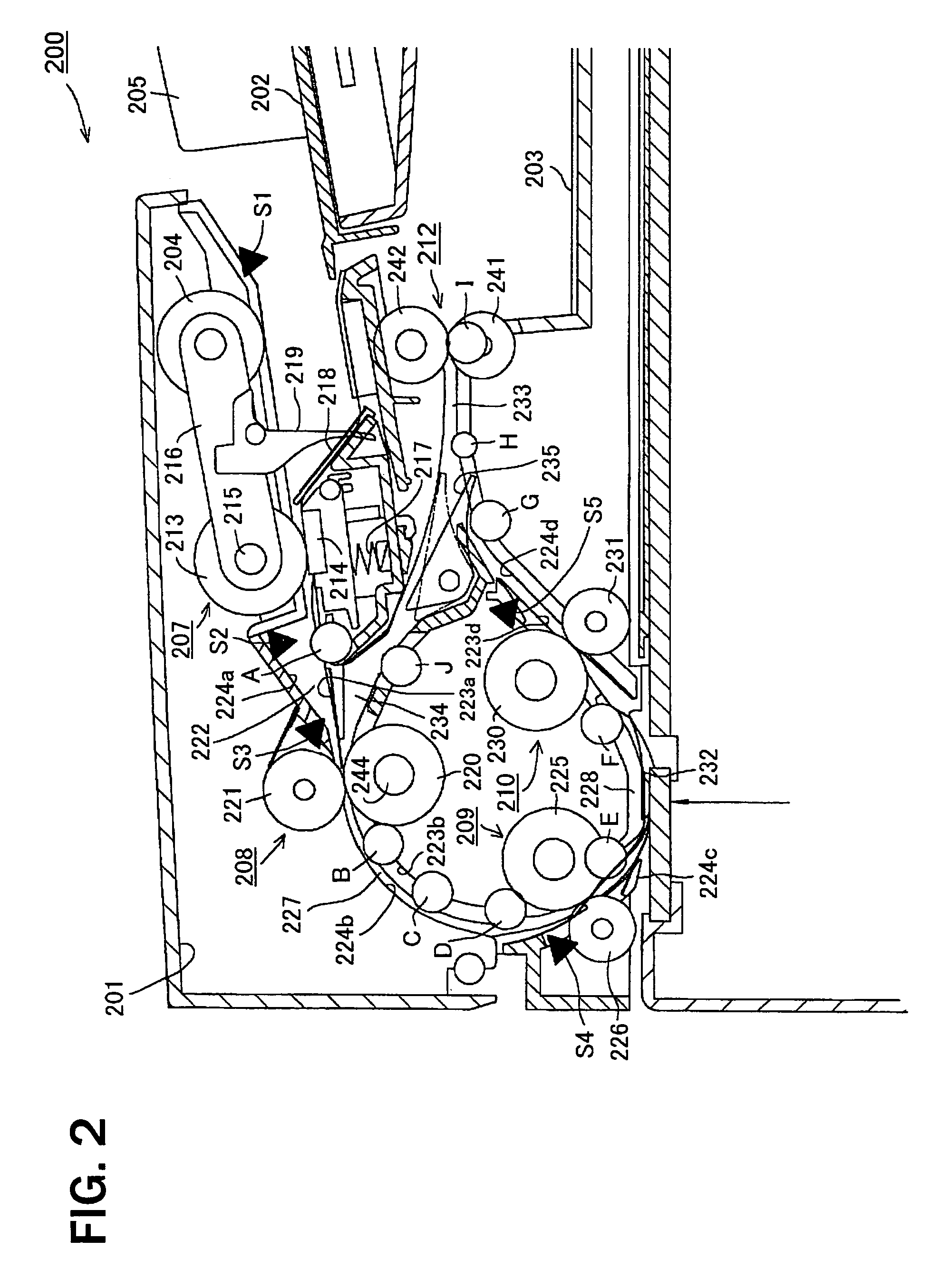
[0047]Hereunder, embodiments of the present invention will be described below in detail with reference to the accompanying drawings. The figures show embodiments in which the present invention is applied to an image reading apparatus. FIG. 1 is a view illustrating the whole image reading apparatus. FIG. 2 is a view illustrating an essential part of a sheet supplying apparatus. FIG. 3 is a view illustrating idle rollers arranged in a U-shaped path.

[0048]In FIG. 1, the image reading apparatus is composed of an image reading unit 100 and a sheet supplying unit 200. The units are incorporated into independent casings 101 and 201, respectively. The image reading unit 100 is composed of platens 103 and 103 incorporated into the casing 101 for placing original sheets (documents); a data reading section (image reading means) 104 for optically reading an image on each sheet on the platen; a data processing section 105 for processing an image signal from the reading section; and a data output...


PUM


Abstract

A sheet supplying apparatus includes a sheet feeding stacker for storing the sheet; a sheet discharging stacker arranged in parallel to the sheet feeding stacker in a vertical direction for storing the sheet; a U-shape conveying path disposed between the sheet feeding stacker to the sheet discharging stacker for guiding the sheet from the sheet feeding stacker to the sheet discharging stacker; a processing platen disposed in the conveying path for processing the sheet; a separating device for separating the sheet on the sheet feeding stacker; a register device for temporarily stopping the sheet and conveying the sheet; a sheet feeding device for conveying the sheet; and a sheet conveying device for conveying the sheet. A sheet discharging device discharges the sheet to the sheet discharging stacker, and an idle roller is disposed in the U-shape conveying path for contacting the sheet to rotate.

Description

BACKGROUND OF THE INVENTION AND RELATED ART STATEMENT[0001]The present invention relates to a sheet supplying apparatus for sequentially separating a sheet stacked on a stacker and supplying the sheet to a processing platen, so that an image on the sheet is read at the processing platen or the sheet is printed, and also relates to an image reading apparatus such as a copier or a scanning device comprising the sheet supplying apparatus.[0002]In general, a sheet supplying apparatus sequentially separates and delivers a sheet stacked on a sheet feeding stacker to a processing platen such as an image reading platen or a printing platen for processing, and discharges the processed sheet to a sheet discharging stacker. The sheet supplying apparatus is also used as a scanner device for reading an image or as a document feeding apparatus of a copier.[0003]In a conventional sheet supplying apparatus such as a scanner apparatus or a copying apparatus, in many cases, a sheet feeding stacker an...

Claims


Application Information

Patent Timeline
Patent Type & Authority Patents(United States)
IPC IPC(8): G03G15/00B65H29/00H04N1/00
CPCH04N1/00567H04N1/00588H04N1/00591H04N1/00631H04N1/00615H04N1/0062H04N1/00628H04N1/00602
Inventor HAMADA, MASATAKANODA, TETSUYAJINZA, OSAMU
Owner NISCA KK
Learn More