
Adjustable position tool guide

Inactive Publication Date: 2006-04-04
NELSON JAMES
View PDF36 Cites 35 Cited by
  • Summary
  • Abstract
  • Description
  • Claims
  • Application Information

AI Technical Summary

Benefits of technology

[0013]A significant advantage of the present invention is that it provides a guide for the movement of a power saw for either right or left handed users, regardless of which side of the work piece the user is working. Further, the tool guide of the present invention provides the user with an accurate, visually observable measurement of the distance between the end of the work piece and the blade of the power saw without requiring the user to adjust the measurement indicated by a tape measure. The tool guide of the present invention may also be easily adapted to work pieces with various widths. Additionally, auxiliary support mat be provided to the tape of a tape measure used with the guide when large distances are to be measured.

Problems solved by technology

However, the typical configuration of portable circular power saws is irregular in the sense that the housing extends for a significant distance from one side of the saw beyond one lateral edge of the shoe, while the housing does not extend beyond the other lateral edge of the shoe.
Typically, the protruding housing interferes with the movement of one of the lateral sides of the shoe along the known guides, especially those guides that employ conventional measuring tape devices that tend to extend upwardly from the surface of the work piece, and interfere with the movement of the protruding housing.
As a result, only the lateral side over which the housing of the saw does not extend is able to slide along the guides.
This can be problematic as this requires the user of the saw to either only use one hand to hold the saw (regardless of whether the user is right-handed or left-handed) or position himself or herself on only one side of the work piece (but not the other).
This has significantly limited the usefulness of such guide devices.
Another difficulty that limits the known guide devices is the ability to accurately measure the distance between the end of the work piece and the operative edge of the guide, or more usefully, the saw blade of the saw as the saw is moved along the operative edge of the guide device.
This requires repeated calculations at each measurement, and introduces the possibility of measurement errors when numerous measurements are made, even when the adjustment to the measurement is deemed to be simple.

Method used


Image

  • Adjustable position tool guide
  • Adjustable position tool guide
  • Adjustable position tool guide

Examples


Embodiment Construction

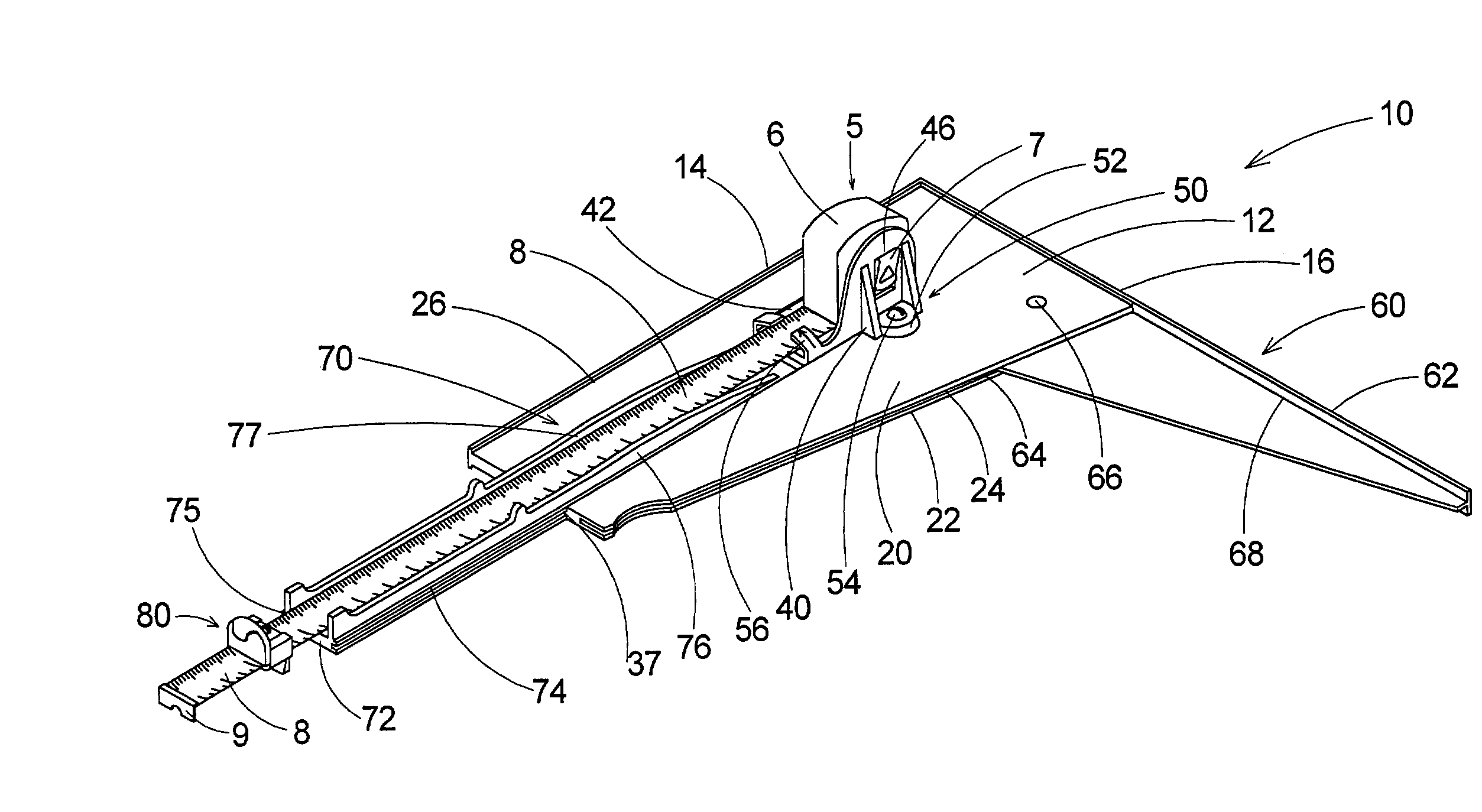
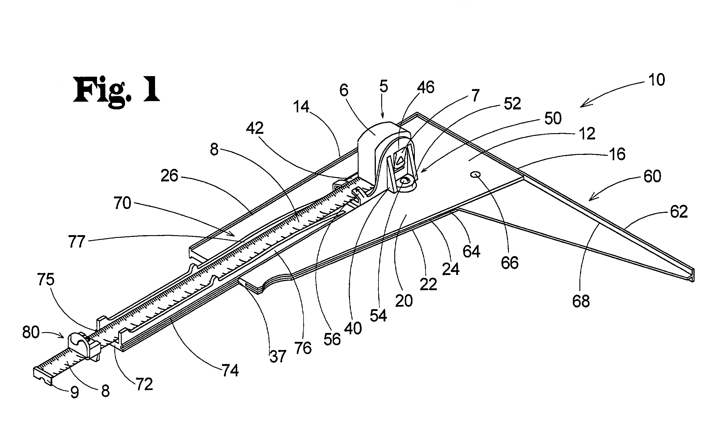
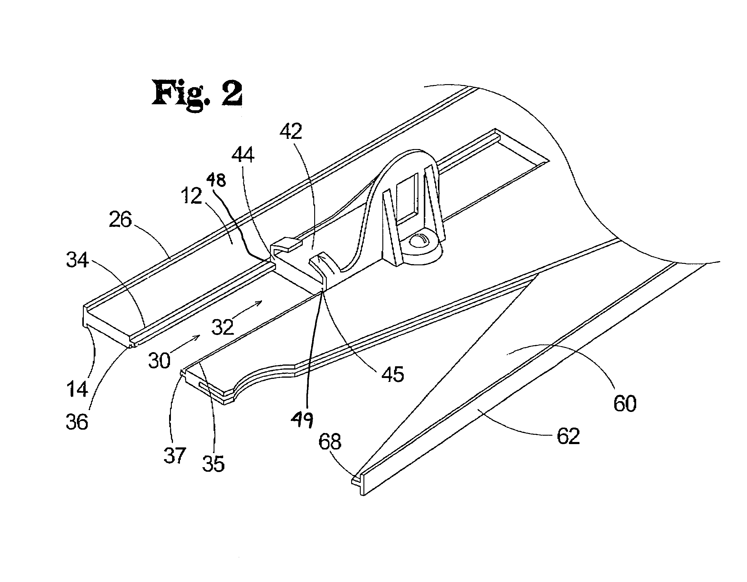
[0021]With reference now to the drawings, and in particular to FIGS. 1 through 5 thereof, a new adjustable position tool guide embodying the principles and concepts of the present invention and generally designated by the reference numeral 10 will be described.

[0022]As best illustrated in FIGS. 1 through 5, the adjustable position tool guide 10 may be used on a work piece 2 having an end 4 or edge (or other feature of the work piece} from which the user needs to measure and perform an operation. The tool guide 10 is suitable for positioning at an adjustable distance from the end 4 of the work piece 2 for facilitating operations on the work piece that require the establishment and maintenance of a stable edge at a selected distance on the work piece, such as, for example, marking the work piece with a marking tool or guiding the movement of a saw or other tool with respect to the work piece. The tool guide is suitable for use with an otherwise conventional tape measure 5 having a hou...


PUM


Abstract

An adjustable position tool guide is disclosed for performing operations with tools on a work piece at an accurate distance and orientation with respect to edges or other features of the work piece in a highly convenient manner. The tool guide includes a base for positioning on the work piece. The base has a base edge for aligning in a substantially parallel orientation to a longitudinal axis of the work piece, and a work edge oriented perpendicular to the base edge for being oriented perpendicular to the longitudinal axis of the work piece when the base edge is aligned parallel with the longitudinal axis. The guide also includes a tape measure mounting assembly mounted on the base for mounting a tape measure on the base. The tape measure mounting assembly is slidably moveable on the base along a line oriented substantially parallel to the base edge of the base.

Description

BACKGROUND OF THE INVENTION[0001]1. Field of the Invention[0002]The present invention relates to tool guides and more particularly pertains to a new adjustable position tool guide for performing operations with tools on a work piece at an accurate distance and orientation with respect to edges or other features of the work piece in a highly convenient manner.[0003]2. Description of the Prior Art[0004]Devices have been proposed and produced that are designed to guide the movement of tools with respect to a work piece in a particular orientation to the geometry of the work piece. These guides are often used to guide the movement of a saw, such as a power saw, across a work piece to cut the work piece to a desired length.[0005]While the use of such guides can be useful, especially when a large number of work pieces need to be cut to various lengths, the guides are most useful if a lateral side of the shoe of the power saw can be slid along a portion of the guide that is oriented substa...

Claims


Application Information

Patent Timeline
IPC IPC(8): G01B3/10B25H7/00B26B29/06B43L7/00B43L7/02B43L13/00B43L13/02
CPCB25H7/00B26B29/06B43L7/005B43L7/02B43L13/02B43L13/002G01B2003/1048G01B3/1056G01B3/1084G01B3/1048
Inventor NELSON, JAMES
Owner NELSON JAMES
Learn More