Method and apparatus for decelerating and temporarily accumulating a hot rolled product

a technology of hot rolled products and deceleration, which is applied in the direction of flexible work arrangements, manufacturing tools, transportation and packaging, etc., can solve the problems of unacceptably low, fire cracking of work rolls, and becoming impractical

a technology of hot rolled products and deceleration, which is applied in the direction of flexible work arrangements, manufacturing tools, transportation and packaging, etc., can solve the problems of unacceptably low, fire cracking of work rolls, and becoming impractical

US7021103B2Inactive Publication Date: 2006-04-04PRIMETALS TECH USA

Image

  • Method and apparatus for decelerating and temporarily accumulating a hot rolled product
  • Method and apparatus for decelerating and temporarily accumulating a hot rolled product
  • Method and apparatus for decelerating and temporarily accumulating a hot rolled product

Examples


Embodiment Construction

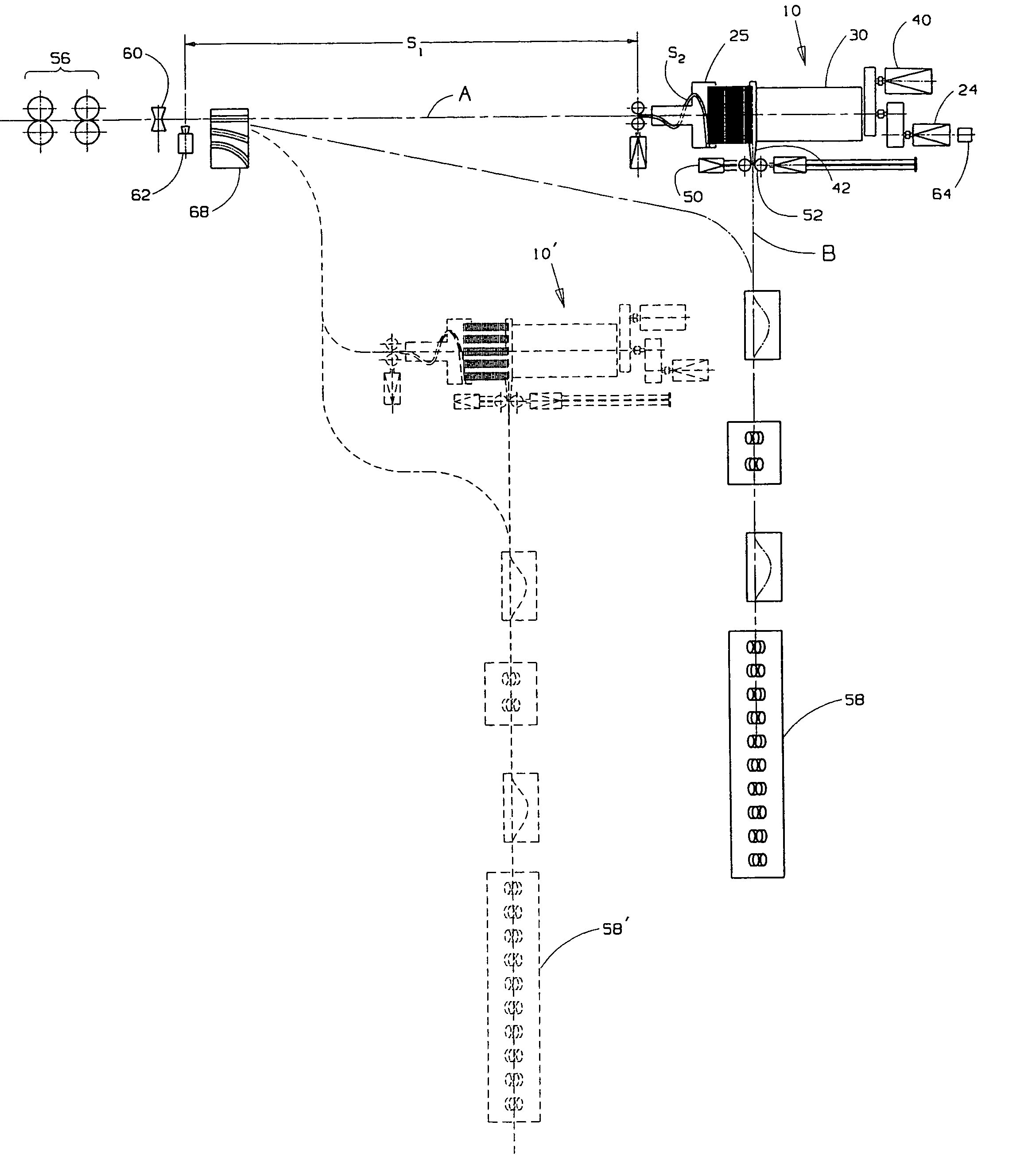
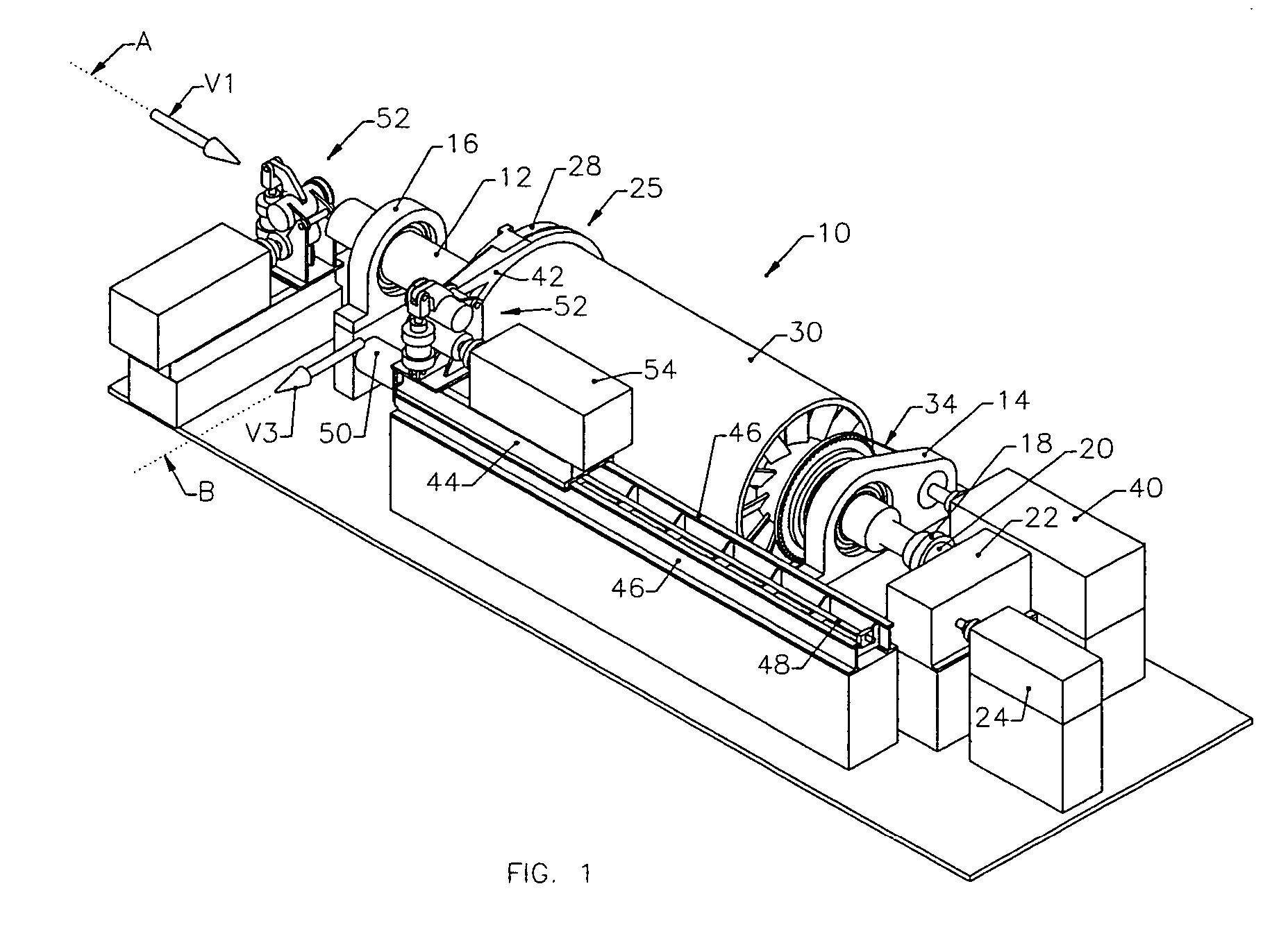
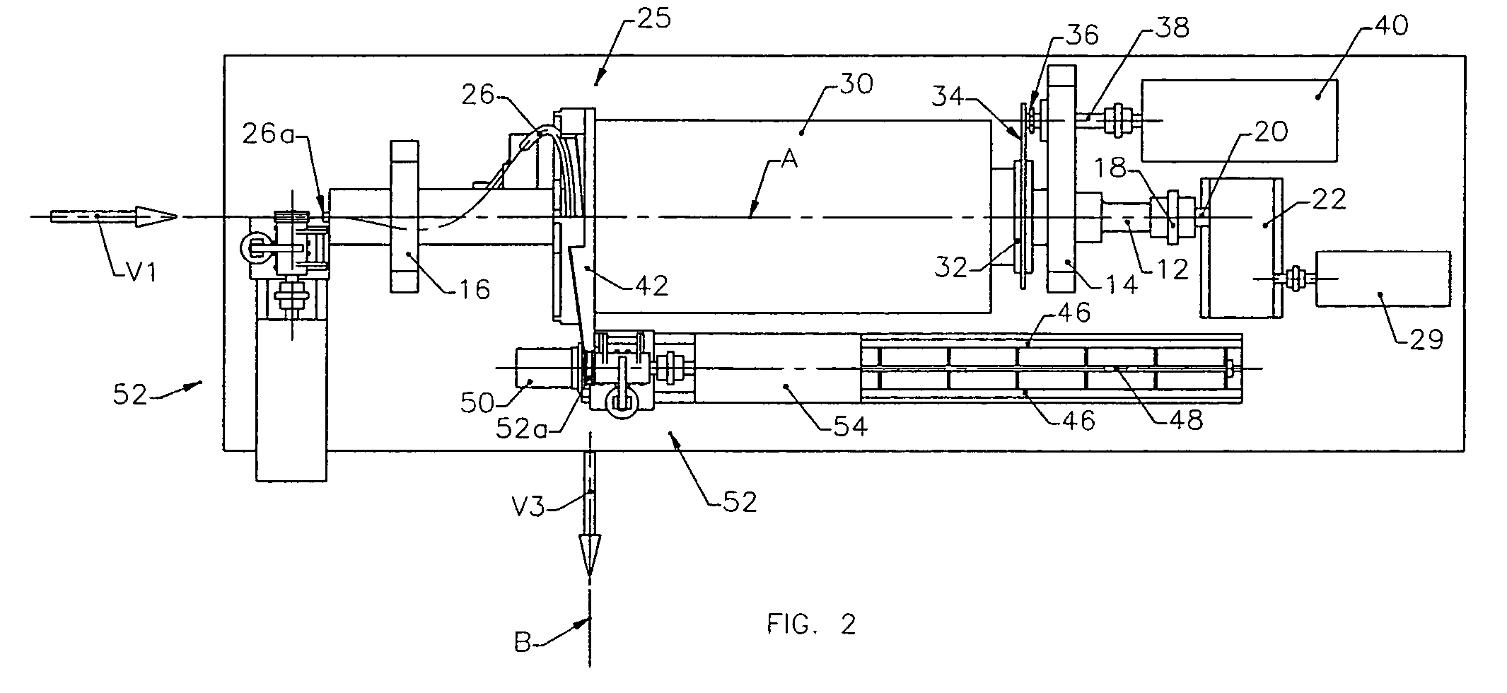
[0025]Referring initially to FIGS. 1–5, an apparatus in accordance with the present invention is generally depicted at 10 as comprising a laying head drive shaft 12 supported between bearings 14, 16 for rotation about a receiving axis A along which hot rolled product is received at a first velocity V1. One end of the drive shaft is coupled as at 18 to the output shaft 20 of a gear box 22, which in turn is driven by a motor 24.

[0026]The opposite end of the drive shaft is configured and arranged to support a curved laying assembly 25 comprising a laying pipe 26 and a helical trough extension 28.

[0027]As can best be seen in FIG. 6, the laying pipe has an entry end 26a aligned with the axis A to receive the hot rolled product, and a curved intermediate section 26b leading to an exit end 26c communicating with the entry end 28a of the helical trough 28. The exit end 28b of the trough is spaced radially from the axis A and oriented to deliver the product in an exit direction along an axis...


PUM

PropertyMeasurementUnit
lengthaaaaaaaaaa
diameteraaaaaaaaaa
speedaaaaaaaaaa

Abstract

A method and apparatus is disclosed for decelerating and temporarily accumulating a hot rolled product moving longitudinally along a receiving axis at a first velocity V1. The product is directed through a curved guide having an entry end aligned with the receiving axis to receive the product, and an exit end spaced radially from the receiving axis and oriented to deliver the product in an exit direction transverse to the receiving axis. The curved guide is rotated about the receiving axis in a direction opposite to the exit direction of the product and at a speed at which the guide exit end has a velocity V2, thereby decelerating the product being delivered from the guide exit end to a reduced velocity V3 equal to V1−V2. The curvature of the guide and the orientation of its exit end is such as to form the delivered product into a helix deposited and temporarily accumulated on a cylindrical drum. The drum is rotated in a direction opposite to the direction of rotation of the curved guide to thereby unwind the product from the drum.

Description

CROSS REFERENCE TO RELATED APPLICATION[0001]This application claims priority of Provisional Application Ser. No. 60 / 470,265 filed May 14, 2003.BACKGROUND OF THE INVENTION[0002]1. Field of the Invention[0003]This invention relates in general to continuous rolling mills producing hot rolled long products such as bars, rods and the like, and is concerned in particular with a method and apparatus for decelerating and temporarily accumulating such products at a selected stage in the hot rolling process.[0004]2. Description of the Prior Art[0005]In the typical rolling mill installation, billets are heated to an elevated rolling temperature in a furnace. The heated billets are then subjected to continuous rolling in successive roughing, intermediate and finishing sections of the mill, with each mill section being comprised of multiple roll stands. For larger products, the entire mill can usually be operated at or close to the maximum capacity of the furnace. However, when the rolling sched...

Claims


Application Information

Patent Timeline
04 Apr 2006
Publication
US7021103B2
IPC
B21B41/00; B21B39/08; B21B1/18; B21B39/18; B21B41/08; B21B45/02; B21C47/14; B21C47/18; B21C49/00
CPC
B21B41/00; B21C49/00; B21C47/143; B21C47/18; B21B1/18; B21B39/18; B21B2045/0236; B21B39/002
Inventors
SHORE, T. MICHAEL