
Remote center of motion robotic system and method

a robotic system and remote center technology, applied in the field of robotic devices and methods, can solve the problems of not fully eliminating the use of the mechanism, inherited poor characteristics of the mechanism, and all the limited range of angular motion of the mechanism, and achieve the effect of increasing the do

Inactive Publication Date: 2006-04-04
THE JOHN HOPKINS UNIV SCHOOL OF MEDICINE
View PDF29 Cites 164 Cited by
  • Summary
  • Abstract
  • Description
  • Claims
  • Application Information

AI Technical Summary

Benefits of technology

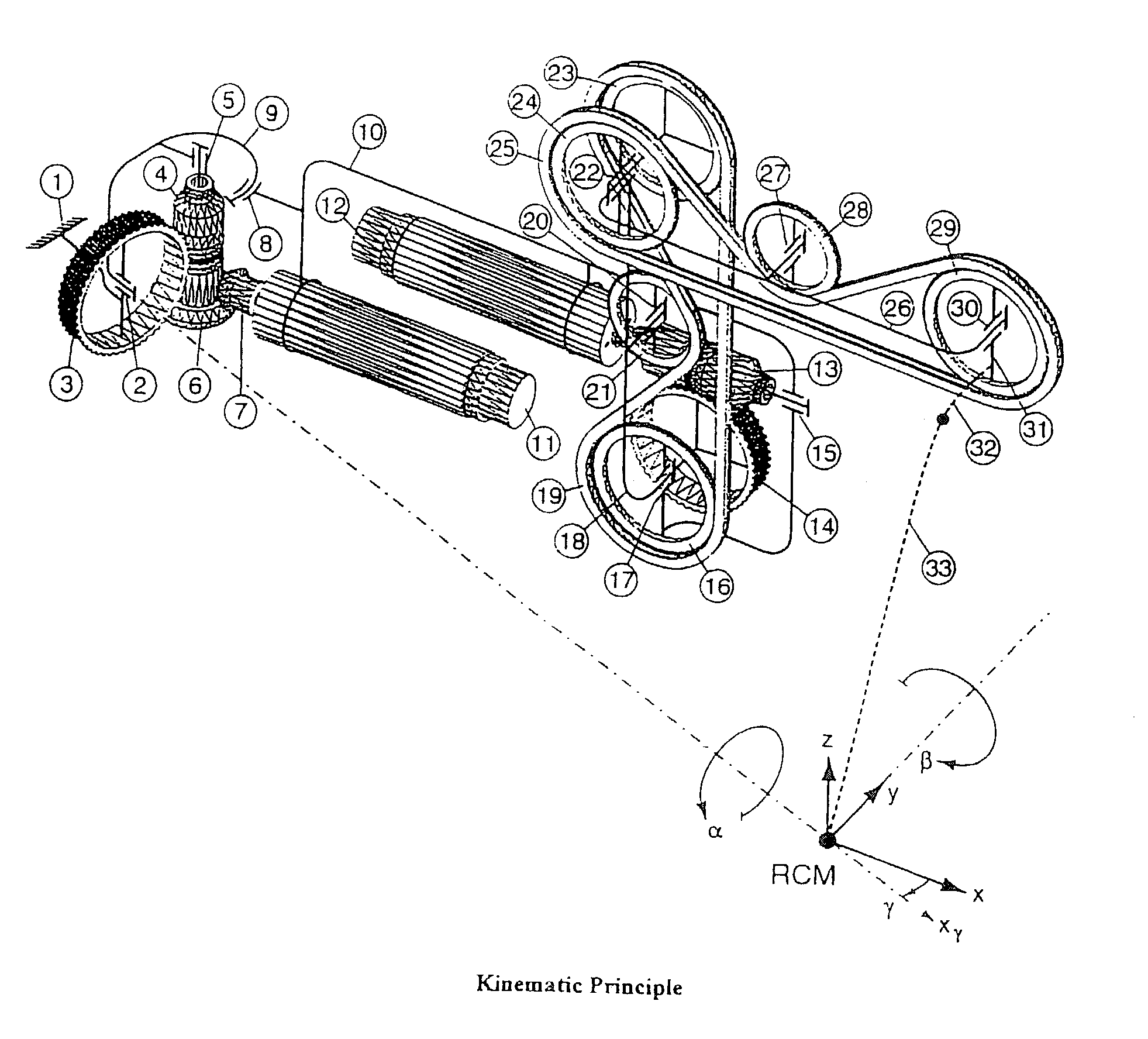
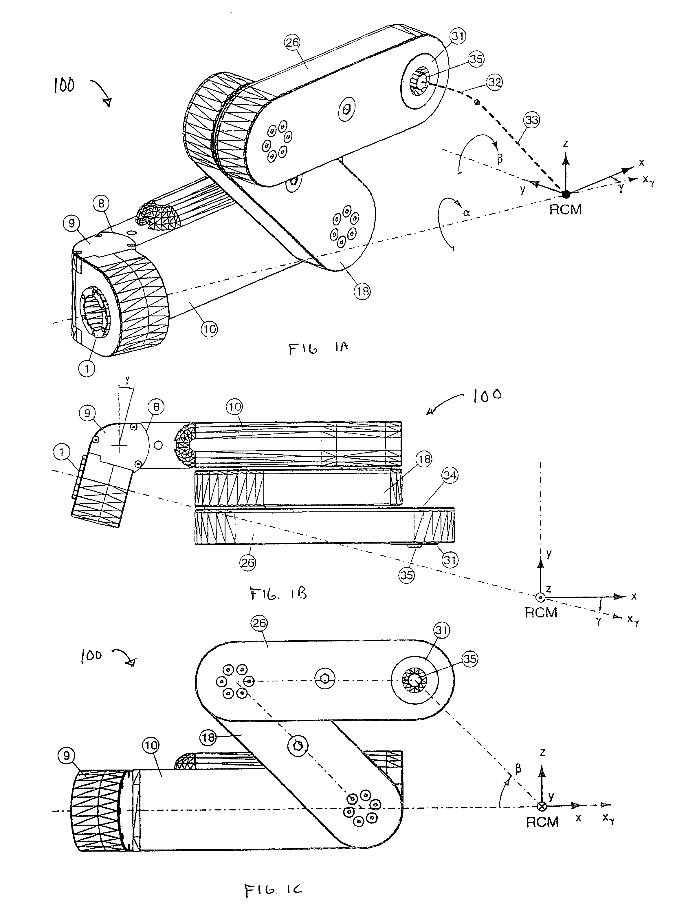
[0021]The present invention is a new RCM device for performing controlled motion in the form of a robotic module. The novelty of this device is that it can attain any rotational orientation without encountering the kinematic singularities that limit the motion of all previously reported mechanisms of rigid linkage RCM designs. With special end-effector adapters the module can manipulate various tools / instruments. The module can be used standalone or in conjunction with other robotic components for increased DOF. It also provides an RCM motion without any part of the mechanism impinging “over” the center of motion (i.e., without the mechanism interfering with free access from the RCM point along a direction orthogonal to the two rotational axes of the RCM mechanism.

Problems solved by technology

All of these mechanisms have limited range of angular motion as a result of their linkage designs.
Although Jensen realized the advantage of replacing the parallel linkage with a continuous transmission, he did not fully eliminate its use.
For this reason, his mechanism inherited certain poor characteristics of the Taylor system: limited range of motion around an upward zero, unequal stiffness at different positions.
This prior art RCM system is also unadjustable and has axes that are orthogonal.
However, these mechanisms are unsafe for surgical applications.
The prior art devices each have limitations that beg improvement.
In particular, rigid linkage RCM designs have limited range of motion.

Method used


Image

  • Remote center of motion robotic system and method
  • Remote center of motion robotic system and method
  • Remote center of motion robotic system and method

Examples


Embodiment Construction

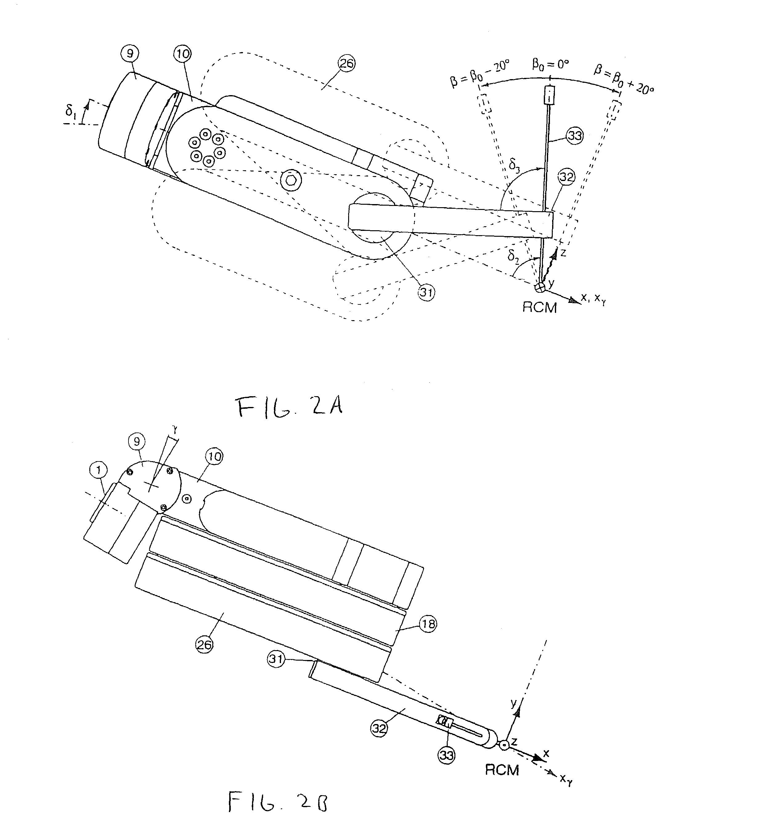
[0032]The present invention provides a novel apparatus and method for performing image assisted surgery. The invention includes a robotic system or module that can be used to orient an end-effector about two axes intersecting at a fixed geometric point, located distal to the mechanism materializing a pivot point, referred to herein as a Remote Center of Motion (RCM). An end-effector, for example, a robotic tool such as a needle driver, may be mounted upon an RCM module and configured to rotate about the RCM point, which can be conveniently located on the end-effector since this point is remote from the robotic module.

[0033]The present invention is configured to allow two rotational degrees-of-freedom (DOF) with coincident axes at the geometric RCM point. The position of the pivot is adjustable along one axis by modifying the relative angle between the axes, referred to herein as the adjustment angle. As such, the two rotations are not necessarily orthogonal.

[0034]Unlike prior art RC...


PUM


Abstract

A remote center of motion robotic system including a base unit and a plurality of linking units. The base unit is rotatable about a first axis. The plurality of linking units are coupled with one another. At least two of the linking units are kept parallel to each another during motion. The plurality of linking units are coupled with that base unit at a first end. The plurality of linking units are rotatable about a second axis by changing an angle between each of the plurality of links.

Description

CROSS REFERENCE TO RELATED APPLICATION[0001]This application claims priority to provisional patent application no. 60 / 354,656, entitled ADJUSTABLE REMOTE CENTER OF MOTION ROBOTIC MODULE, filed on Feb. 6, 2002, the contents of which are incorporated herein by reference.BACKGROUND OF THE INVENTION[0002]1. Field of the Invention[0003]The present invention relates to robotic devices and methods. In particular, the invention relates to systems and methods for orienting an end-effector about two axes intersecting at a fixed geometric point located distally, materializing a pivot point or a Remote Center of Motion (RCM).[0004]2. Description of the Related Art[0005]In robotics the pivot point and kinematic principle used is commonly referred to as the Remote Center of Motion. Systems and methods for orienting parts, tools, and instruments about a RCM point distal to the mechanism are well known. For example, see U.S. Pat. Nos. 5,397,323, 5,515,478, 5,630,431, 5,817,084, 5,907,664, 6,047,610...

Claims


Application Information

Patent Timeline
IPC IPC(8): B25J17/00B25J9/00A61B19/00B25J9/06B25J9/10B25J17/02B25J18/00
CPCA61B19/2203B25J9/06B25J9/104B25J17/025B25J18/007B25J9/102A61B2019/2234A61B2019/2242A61B2019/2246A61B2019/265Y10T74/20317Y10T74/20329Y10T74/20323A61B2034/715A61B2090/506A61B34/71A61B34/30A61B2034/305
Inventor STOIANOVICI, DANWHITCOMB, LOUIS L.MAZILU, DUMITRUTAYLOR, RUSSELL H.KAVOUSSI, LOUIS R.
Owner THE JOHN HOPKINS UNIV SCHOOL OF MEDICINE
Learn More