Determining gradients using a multi-probed formation tester

Inactive Publication Date: 2006-04-04
HALLIBURTON ENERGY SERVICES INC
View PDF15 Cites 18 Cited by
  • Summary
  • Abstract
  • Description
  • Claims
  • Application Information

AI Technical Summary

Benefits of technology

[0021]A multi-probe tester also allows enough separate measurements of formation, wellbore, and flowline pressure to enable meaningful statistical analysi

Problems solved by technology

The mudcake also limits the migration of drilling fluids from the area of high hydrostatic pressure in the wellbore to the relatively low-pressure formation.
These m

Method used


Image

  • Determining gradients using a multi-probed formation tester
  • Determining gradients using a multi-probed formation tester
  • Determining gradients using a multi-probed formation tester

Examples


Embodiment Construction

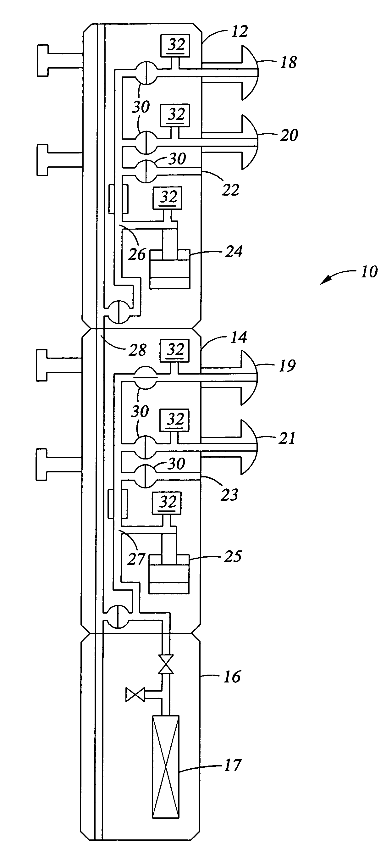
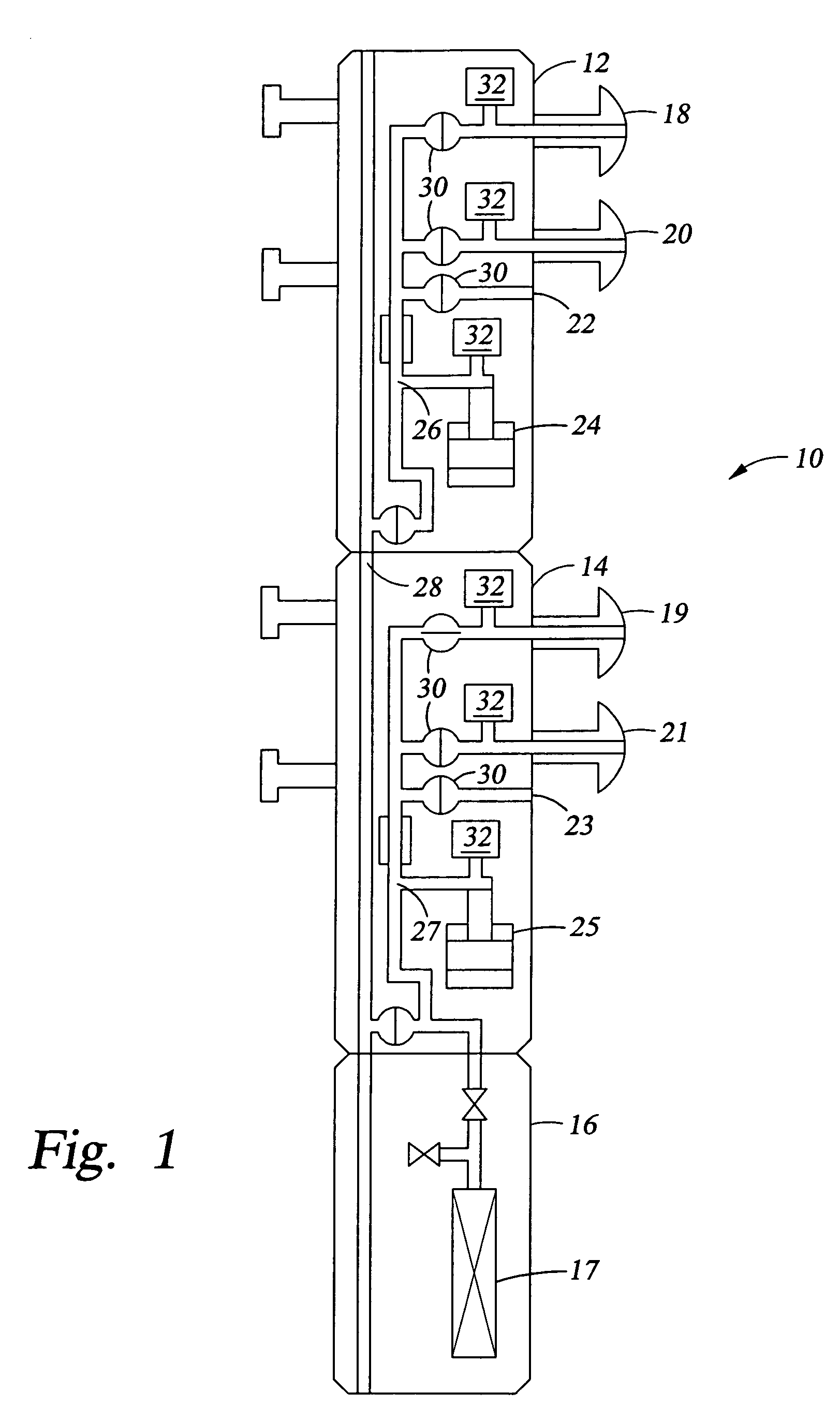
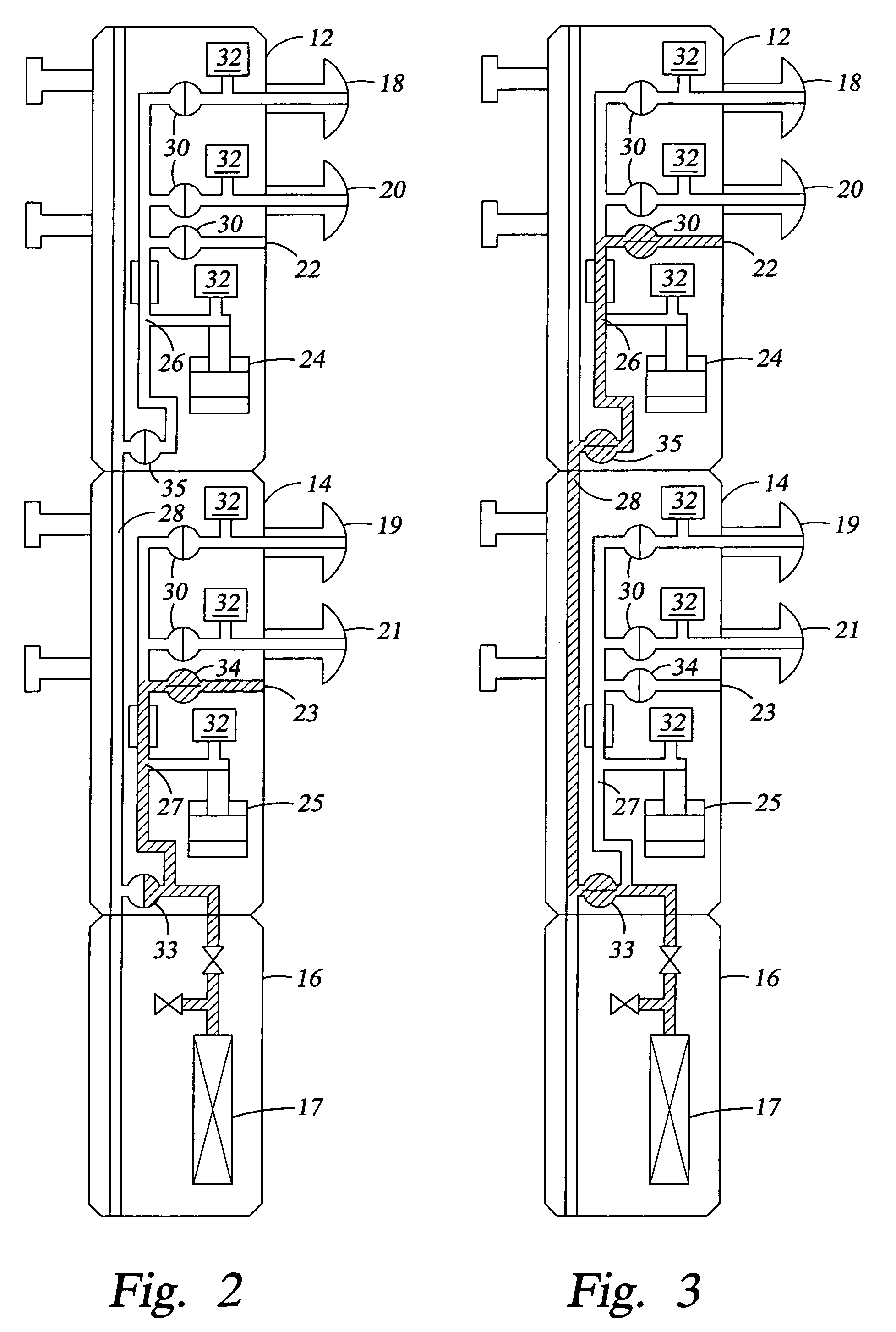
[0016]Embodiments of the invention include methods for operating multi-probed formation testers to determine a fluid density gradient in the formation. The probes of the multi-probed formation tester are connected to a pressure gauge through a flowline that establishes a differential height between the probes. In some embodiments, a gradient of the fluid density in the flowline is determined as a function of the gradient of fluid density in the wellbore. The flowline fluid density gradient is then used to determine a formation fluid density gradient as a function of the flowline fluid density gradient.

[0017]The preferred embodiments provide methods for calculating pressure gradients in multi-probed formation testers that compensate for flowline differential pressure created by varying distances between the tester probes and the pressure sensors. One method includes determining the wellbore gradient by taking a pressure measurement from the wellbore from two pressure ports in the flo...


PUM


Abstract

Methods for operating multi-probed formation testers to determine a fluid density gradient in the formation. The probes of the multi-probed formation tester are connected to a pressure gauge through a flowline that establishes a differential height between the probes. In some embodiments, a gradient of the fluid density in the flowline is determined as a function of the gradient of fluid density in the wellbore. The flowline fluid density gradient is then used to determine a formation fluid density gradient as a function of the flowline fluid density gradient.

Description

CROSS-REFERENCE TO RELATED APPLICATIONS[0001]This application claims priority to U.S. Provisional Patent Application 60 / 467,329, filed May 2, 2003, and entitled “Determining Gradients using a Multi-probed Formation Tester,” which is hereby incorporated by reference herein for all purposes.STATEMENT REGARDING FEDERALLY SPONSORED RESEARCH OR DEVELOPMENT[0002]Not applicable.BACKGROUND OF THE INVENTION[0003]The embodiments of the present invention relate generally to methods for determining pressure gradients in a wellbore. More specifically, the embodiments relate to methods for determining formation pressure gradients using multiple pressure readings from different depths in the wellbore.[0004]Due to the high costs associated with drilling and producing hydrocarbon wells, optimizing the performance of wells has become very important. The acquisition of accurate data from the wellbore is critical to the optimization of the completion, production and / or rework of hydrocarbon wells. This...

Claims


Application Information

Patent Timeline
IPC IPC(8): G06F19/00E21BE21B49/00E21B49/08G01NG01N9/00G01N9/26G01N15/08G01V1/40G01V3/18G01V5/04
CPCE21B49/005G01N9/26E21B49/087E21B49/08G16Z99/00G01N15/08G01V1/40G01V3/18G01V5/04G01V9/00E21B49/0875
Inventor PROETT, MARK A.GILBERT, GREGORY N.BALL, DAVID E.
Owner HALLIBURTON ENERGY SERVICES INC
Why Eureka
Try Eureka