Airbag device

Inactive Publication Date: 2006-04-04
HONDA MOTOR CO LTD
View PDF10 Cites 16 Cited by
  • Summary
  • Abstract
  • Description
  • Claims
  • Application Information

AI Technical Summary

Benefits of technology

[0014]According to an aspect of the present invention, there is provided an airbag device which comprises: a bag housing case; an airbag housed in a folded or deflated state in the bag housing case; a plate member disposed within and connected to the airbag; and a bag pressure release mechanism provided in the bag housing case in opposed relation to an inside of the airbag, the mechanism being designed to open the ai

Problems solved by technology

It is conceivable that an obstacle after striking the front bumper of a vehicle again strikes another portion of the vehicle.
When collided by an obstacle, an airbag having a high internal pressure for mitigating a secondary collision of the obstacle, however, can fail to sufficiently mitigate an impact on the obstacle.
A vehicle having a relatively long distance between the front bumper and the windshi

Method used


Image

  • Airbag device
  • Airbag device
  • Airbag device

Examples


first embodiment

[0054]FIGS. 2 to 10 illustrate an airbag device according to a

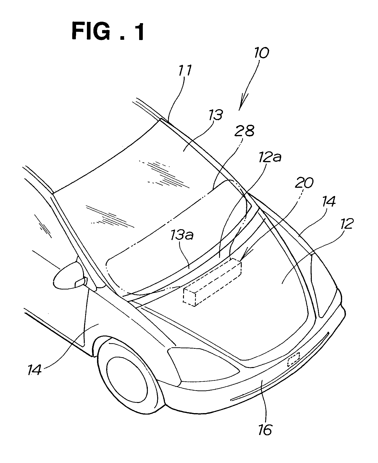
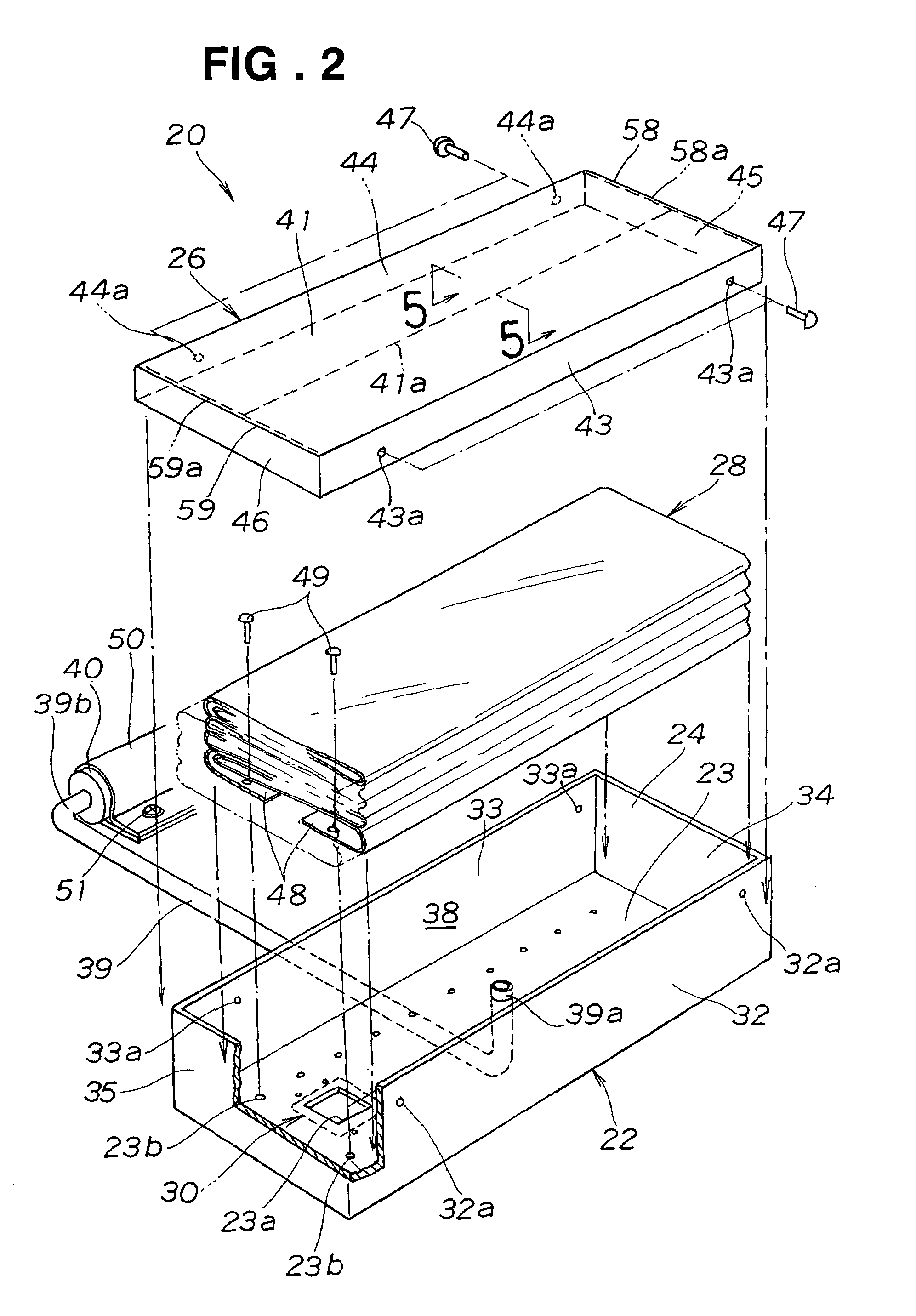
[0055]Referring to FIG. 2, the airbag device 20 in the first embodiment is provided mainly with a bag housing case 22 provided below the rear end 12a of the bonnet 12 shown in FIG. 1, a cover 26 closing an opening 24 of the bag housing case 22, the airbag 28 housed in the bag housing case 22, and a bag pressure release mechanism 30 provided at the bottom 23 of the bag housing case 22.

[0056]The bag housing case 22 has the bottom 23 formed in a rectangular shape and front, rear, left and right sidewalls 32, 33, 34 and 35 provided at the front, rear, left and right sides of the bottom 23, thereby forming a housing space 38. In the housing space 38, the airbag 28 made from a flexible material is housed in a folded state.

[0057]A vent hole 23a formed in the bottom 23 is closable by the bag pressure release mechanism 30. A distal end 39a of a gas supply pipe 39 is protruded through the bottom 23 into the housing space 38. A plur...

second embodiment

[0096]Now, an inflating operation of the airbag device 70 in the second embodiment will be described with reference to FIGS. 15 to 17.

[0097]In FIG. 15, when a vehicle 10 shown in FIG. 1 collides with an obstacle, an igniter (not shown) is energized, igniting an inflator 40 (see FIG. 4). A high pressure gas generated by the inflator 40 shown in FIG. 4 flows through a gas supply pipe 39 into the airbag 28. The airbag 28 starts inflating under the gas pressure. The top 28a of the airbag 28 abuts on the inner surface of a cover plate 41 of a cover 26.

[0098]From this state, gas continuously flows into the airbag 28, increasing the internal pressure of the airbag 28 to a predetermined pressure P1, and causing a predetermined boosting force acting on the cover plate 41. The boosting force causes breakage of the cover plate 41 at a central tear seam 41a at the center, a left tear seam 58a at a left corner 58 and a right tear seam 59a at a right corner 59 shown in FIG. 2.

[0099]At that time, ...

third embodiment

[0110]FIGS. 18 to 20 illustrate an airbag device according to the present invention.

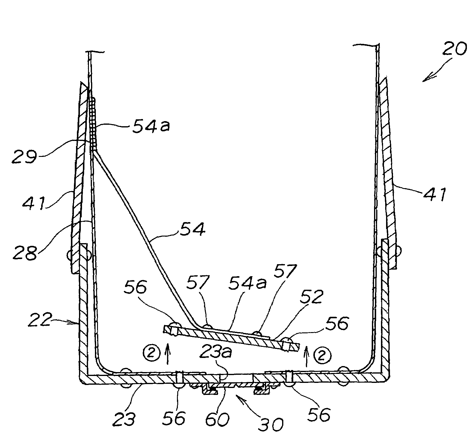
[0111]An airbag device 75 in the third embodiment has a lifting member 76 positioned at a predetermined height H from bottom edges 48, 48 of an airbag 28 as shown in FIG. 19. Opposite ends 76a, 76a of the lifting member 76 are stitched to a sidewall 29 of the airbag 28. A distal end 77a of a strap 77 is stitched to the lifting member 76. A proximal end 77b of the strap 77 is fastened to a plate member 52 with screws 57, 57. The other components are identical with those of the airbag device 20 in the first embodiment.

[0112]The lifting member 76 and the airbag 28 are made from the same flexible material. The lifting member 76 has a plurality of holes 78, 78 formed in desired positions. Gas is fed from an inflator 40 (see FIG. 4) into the airbag 28 through the holes 78, 78.

[0113]The distal end 77a of the strap 77 has left and right extensions which are stitched to the lifting member 76 so that the strap...


PUM


Abstract

An airbag device has a bag housing case, an airbag housed in the bag housing case, a plate member provided within the airbag, and a bag pressure release mechanism. When the internal pressure of the airbag reaches a predetermined pressure, the bag pressure release mechanism opens the airbag to prevent an increase in the internal pressure of the airbag. The plate member covers the bag pressure release mechanism when the airbag is in a deflated state. When the airbag is inflated, the plate member is released from coverage of the bag pressure release mechanism by an inflating force.

Description

FIELD OF THE INVENTION[0001]The present invention relates to an airbag device with an airbag which, when a vehicle carrying the airbag device collides with an obstacle, expands or inflates to mitigate the resultant impact on the obstacle.BACKGROUND OF THE INVENTION[0002]Collisions of vehicles with obstacles have some conceivable patterns. It is conceivable that an obstacle after striking the front bumper of a vehicle again strikes another portion of the vehicle. The first collision of the obstacle with the front bumper is called a “primary collision,” and the next collision with another portion of the vehicle is called a “secondary collision.”[0003]There is an airbag device with an airbag which is inflated with gas generated by an inflator immediately after a primary collision, covering a vehicle outside portion such as an A-pillar or a windshield, and mitigating an impact in a secondary collision of an obstacle with the vehicle outside portion.[0004]When collided by an obstacle, an...

Claims


Application Information

Patent Timeline
IPC IPC(8): B60R21/16B60R21/34B60R21/233B60R21/239B60R21/276B60R21/36
CPCB60R21/2165B60R21/233B60R21/239B60R21/2338B60R2021/23382
Inventor OKAMOTO, YUTAKAKIKUCHI, YUJI
Owner HONDA MOTOR CO LTD
Why Eureka
Try Eureka