Irrigation coupling apparatus and method

a technology of irrigation and coupling, which is applied in the direction of couplings, bends, branching pipes, etc., can solve the problems of relatively unreliable connection, time-consuming process, and unreliable connection, so as to reduce the overall cost and installation time of such fluid systems, and facilitate the connection within fluid systems. the effect of reliable connection

Inactive Publication Date: 2006-04-04
HUSQVARNA AB
View PDF64 Cites 32 Cited by
  • Summary
  • Abstract
  • Description
  • Claims
  • Application Information

AI Technical Summary

Benefits of technology

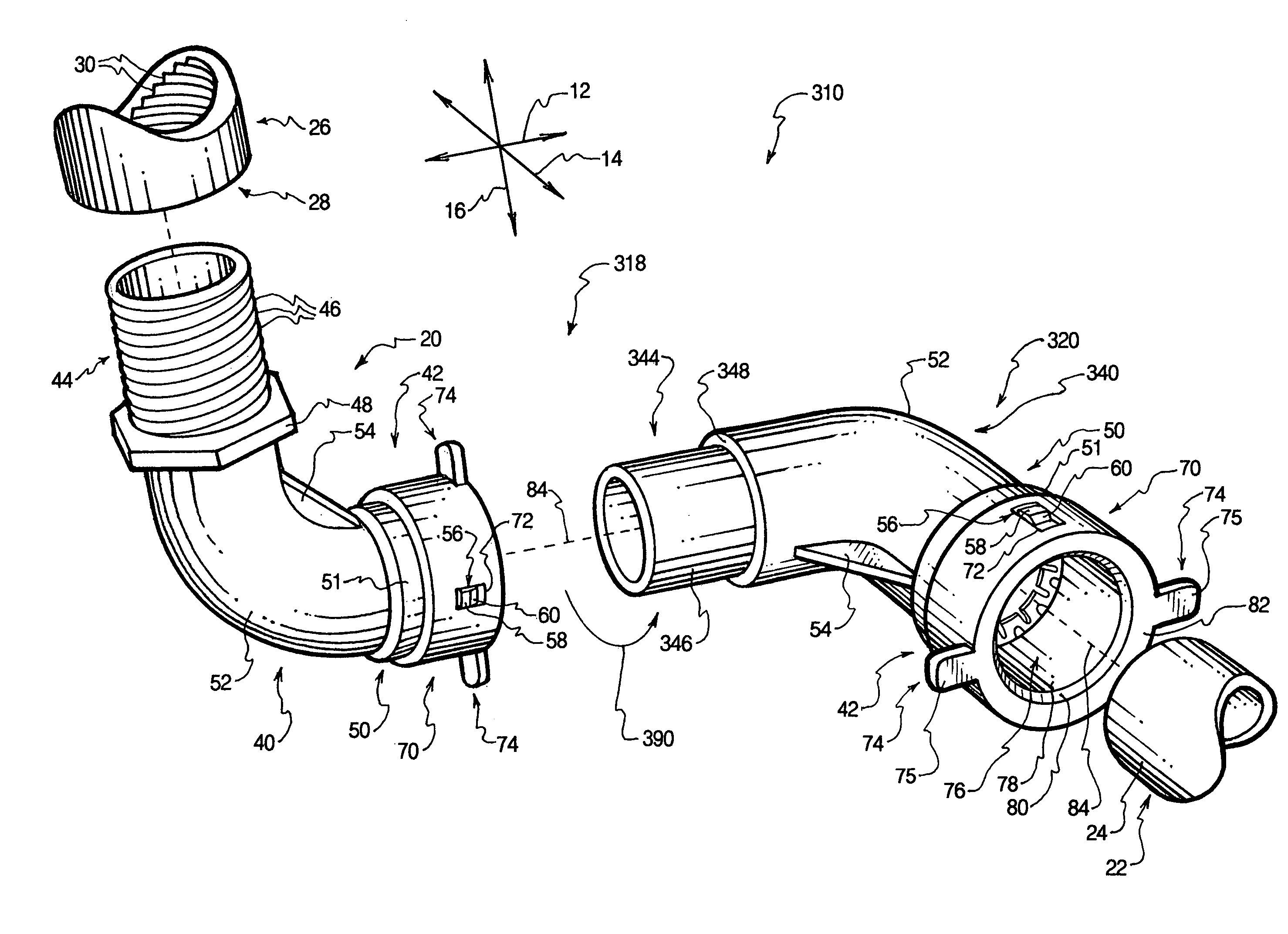
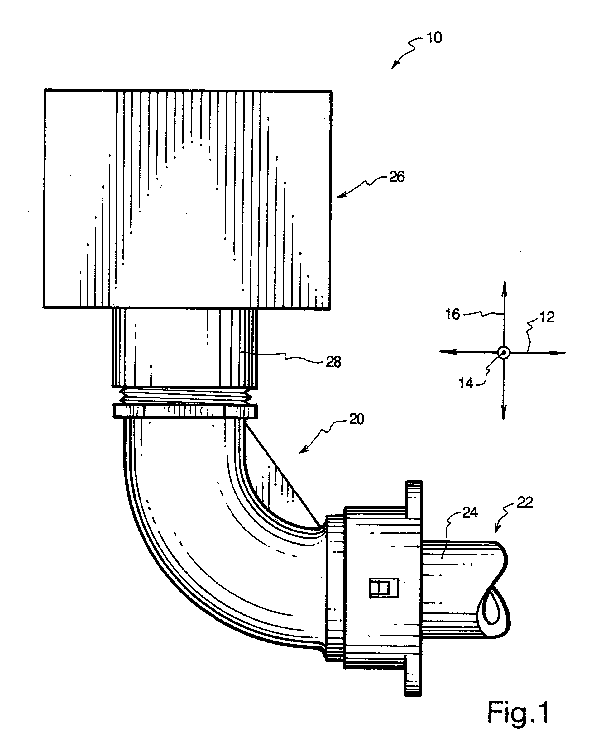
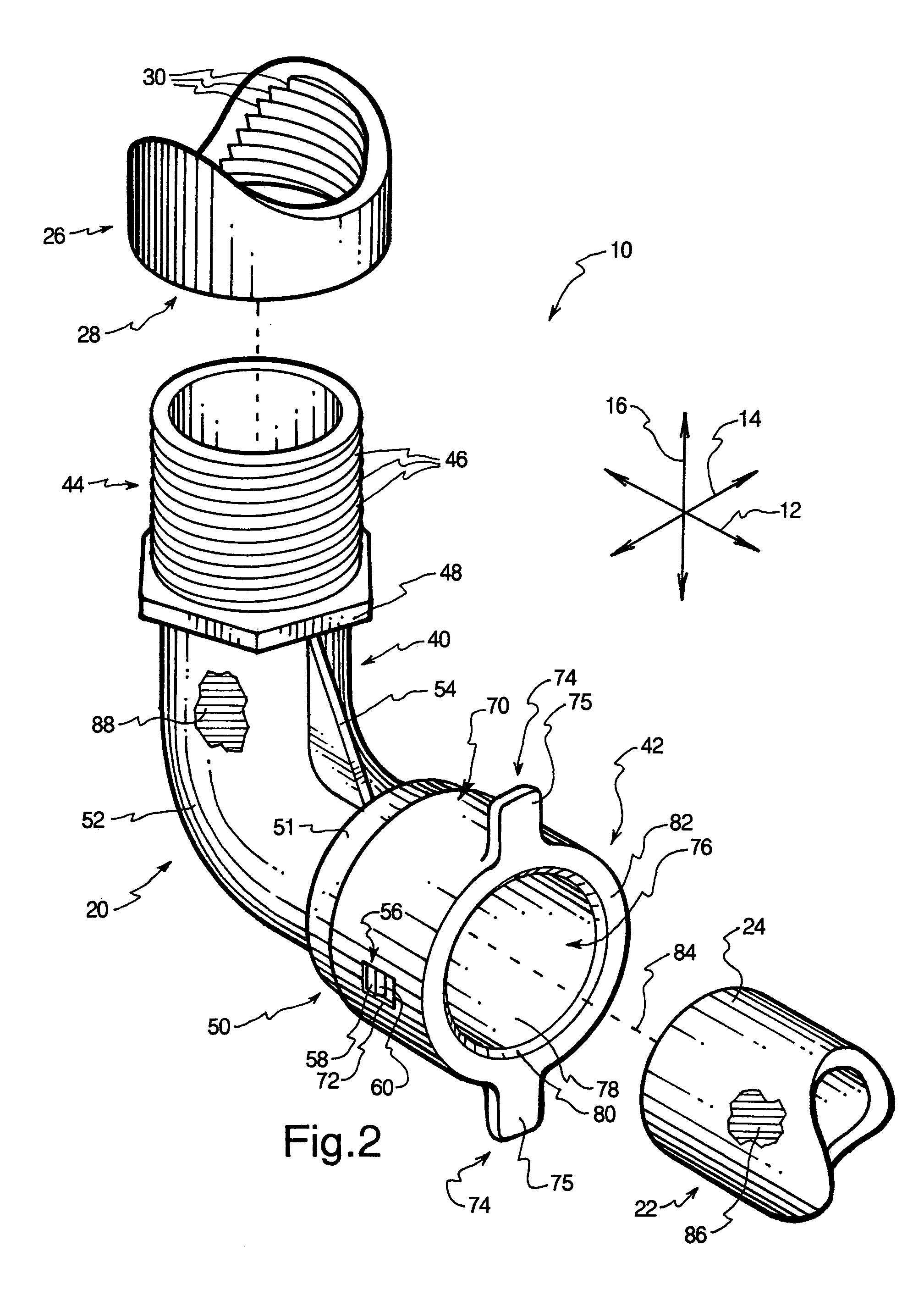
[0016]The release mechanism may take the form of a release ring with an exterior sleeve that encircles the second end. A pair of retention slots are formed in the exterior sleeve in alignment with the retention features such that the retention features protrude into the retention slots. Each of the retention features may have a ramp and a plateau situated such that the ramp tends to widen the exterior sleeve during assembly to enable the exterior sleeve to slide over the retention features until the retention features are situated in the retention slots. The plateaus abut an end of each retention slot to limit the range of motion of the exterior sleeve with respect to the second end.
[0018]The exterior sleeve is sized to provide a very small clearance with the shoulder. Hence, a narrow annular gap exists between the exterior sleeve and the shoulder. The clearance is small enough that dirt is generally unable to enter the annular gap, and is thus unable to impede the motion of the release ring. Hence, the coupling can be buried and subsequently disinterred without reducing the user's ability to disconnect the conduit from the coupling via the release ring.
[0021]A seal ring is seated against a flat step of the bore, inward of the spring washer. The seal ring is formed of a resilient material such as rubber, such that the seal ring is able to form a substantially watertight seal against the outside diameter of the end of the conduit. The seal ring may have a countersink that facilitates insertion of the end of the conduit through the seal ring.
[0032]Through the use of the apparatus and method of the invention, connections within fluid systems may be more easily and reliably made. Furthermore, the overall expense and installation time of such fluid systems may be reduced. These and other features and advantages of the present invention will become more fully apparent from the following description and appended claims, or may be learned by the practice of the invention as set forth hereinafter.

Problems solved by technology

Thus, the process of connecting the conduits to their respective components can be somewhat time-consuming.
Such a process is somewhat time consuming and messy, and provides a relatively unreliable connection.
To the extent that threaded or barbed fittings can be used, connection may be performed more rapidly than with primer and glue, but the integrity of the connection is still uncertain.
Furthermore, a glued connection cannot be released.
Barbed fittings may be difficult for some people to install due to the force required to insert the barbs far enough to provide retention.
Thus, connecting the components and lengths of PVC pipe and / or flexi-pipe together may be somewhat cumbersome and time-consuming.
However, known couplings have a number of inherent disadvantages.
Often, such couplings require primer and glue, threaded attachment, or barbed attachment, and therefore add significantly to the required installation time.
Some couplings are not readily detachable, while others may not function properly under certain conditions, such as when buried underground.
Yet further, many known couplings do not indicate the proper size of conduit to make a fluid-tight connection with the coupling.
Hence, many consumers may accidentally purchase or attempt to connect couplings and flexi-pipe that are incompatible with each other.
Such an arrangement may tend to place undue stress on the flexi-pipe.
The flexi-pipe may thus become weakened, disconnected, or pinched as a result.

Method used


Image

  • Irrigation coupling apparatus and method
  • Irrigation coupling apparatus and method
  • Irrigation coupling apparatus and method

Examples


Embodiment Construction

[0043]The presently preferred embodiments of the present invention will be best understood by reference to the drawings, wherein like parts are designated by like numerals throughout. It will be readily understood that the components of the present invention, as generally described and illustrated in the figures herein, could be arranged and designed in a wide variety of different configurations. Thus, the following mote detailed description of the embodiments of the apparatus, system, and method of the present invention, as represented in FIGS. 1 through 9, is not intended to limit the scope of the invention, as claimed, but is merely representative of presently preferred embodiments of the invention.

[0044]For this application, the phrases “connected to,”“coupled to,” and “in communication with” refer to any form of interaction between two or more entities, including mechanical, electrical, magnetic, electromagnetic, and thermal interaction. The phrase “attached to” refers to a for...


PUM

PropertyMeasurementUnit
angleaaaaaaaaaa
ninety degree angleaaaaaaaaaa
angleaaaaaaaaaa

Abstract

In a fluid system such as irrigation system, fluid conduit attachment is facilitated through the use of a coupling. The coupling may have a body with a first end attached to a component such as an irrigation component, and a second end designed to receive an end of a conduit. The first end may be integrally formed with the component or separately attached thereto. The second end has a bore into which the end of the conduit is inserted. A gripping mechanism is seated in the bore to grip the end of the conduit. A release mechanism slides to release the conduit. The coupling may have a bend and / or branches extending to extra ends. A second coupling may be added to form a rotatable swing joint. An indicator such as a blue color may be used to indicate compatibility of the coupling with the conduit.

Description

RELATED U.S. APPLICATIONS[0001]This application claims the benefit of U.S. Provisional Patent Application Ser. No. 60 / 474,040, filed May 29, 2003 and entitled IRRIGATION COUPLING APPARATUS AND METHOD, which is incorporated herein by reference.BACKGROUND OF THE INVENTION[0002]1. Field of the Invention[0003]The present invention relates to couplings for fluid systems. More specifically, the present invention relates to couplings that may be used to easily retain or release flexible plastic tubing such as that typically used in irrigation systems.[0004]2. Description of Related Art[0005]Many types of systems have components between which fluid is conveyed through conduits. Such fluid systems include irrigation systems, household plumbing, air conditioning systems, heater humidifiers, misting systems, and garden hoses. Typically, the conduits of the fluid system must be coupled to components in such a manner that a fluid-tight seal is maintained. Thus, the process of connecting the cond...

Claims


Application Information

Patent Timeline
Patent Type & Authority Patents(United States)
IPC IPC(8): F16L37/00A61B17/20F16L37/091F16L41/02F16L47/26F16L47/32
CPCF16L37/008F16L37/091F16L47/32F16L43/008F16L41/021F16L37/0915
Inventor ERICKSEN, KENT C.SMITH, ALAN JOHNERICKSEN, MICHAEL RAY
Owner HUSQVARNA AB
Why Eureka
Try Eureka