Archers flame illuminated arrow nock

a technology of flame and arrow nock, which is applied in the field of arrows, can solve the problems of frightening game animals in hunting situations, draining the battery, and dislodging the protected cap, and achieve the effect of reducing weigh

Inactive Publication Date: 2006-04-04
DICARLO JOSEPH L
View PDF2 Cites 65 Cited by
  • Summary
  • Abstract
  • Description
  • Claims
  • Application Information

AI Technical Summary

Benefits of technology

[0015]Accordingly, the object of the present invention is to provide an illuminated arrow nock or insert that can be turned on by the act of shooting the arrow from a traditional bow, compound bow, and or crossbows.
[0016]Second object of the present invention is to provide a new and simplified method of arranging needed components to reduce weight.
[0017]Another object of the present invention is to provide an illuminated nock tha

Problems solved by technology

This system would create a disadvantage and frighten game animals in hunting situations.
Furthermore, do to the deceleration properties of this device it would turn off if shot arrow were to come in contact with a solid object such as a tree, rock, or bone of a hunted animal.
The disadvantage to this system is the protected cap could beco

Method used


Image

  • Archers flame illuminated arrow nock
  • Archers flame illuminated arrow nock
  • Archers flame illuminated arrow nock

Examples


Embodiment Construction

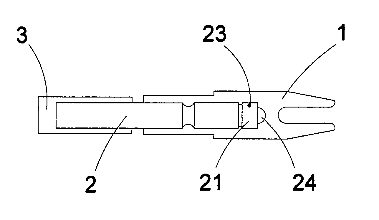
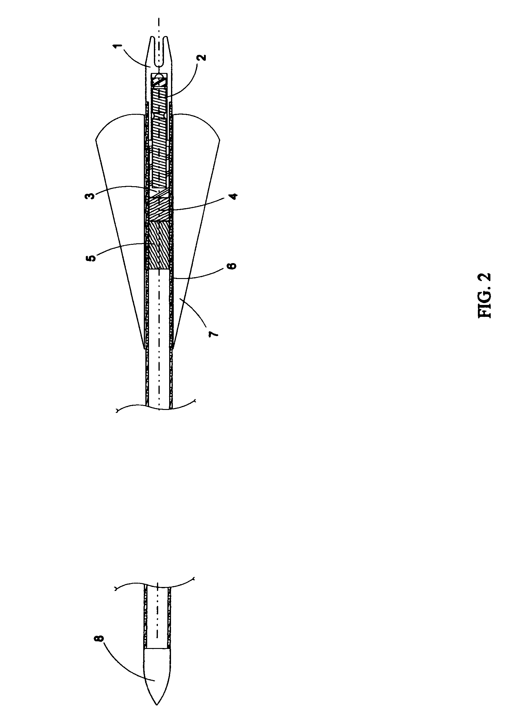
[0047]In the description of this invention the words “closed switch” is to indicate the circuit is energized to the LED light bulb. “Open switch” is to indicate the circuit is not energized to the LED light bulb.

[0048]In the description of this invention the words “anchor pin” indicates a pin made of metal or plastic used to hold or capture said components in a fixed position.

[0049]In the description of this invention the words “dowel” identifies a material made from wood, plastic, or carbon placed inside arrow shaft as a means of limiting forward travel of assembly.

[0050]While the embodiment of the present invention may have a broad scope of uses its premiere application is in conjunction with a lighted arrow nock.

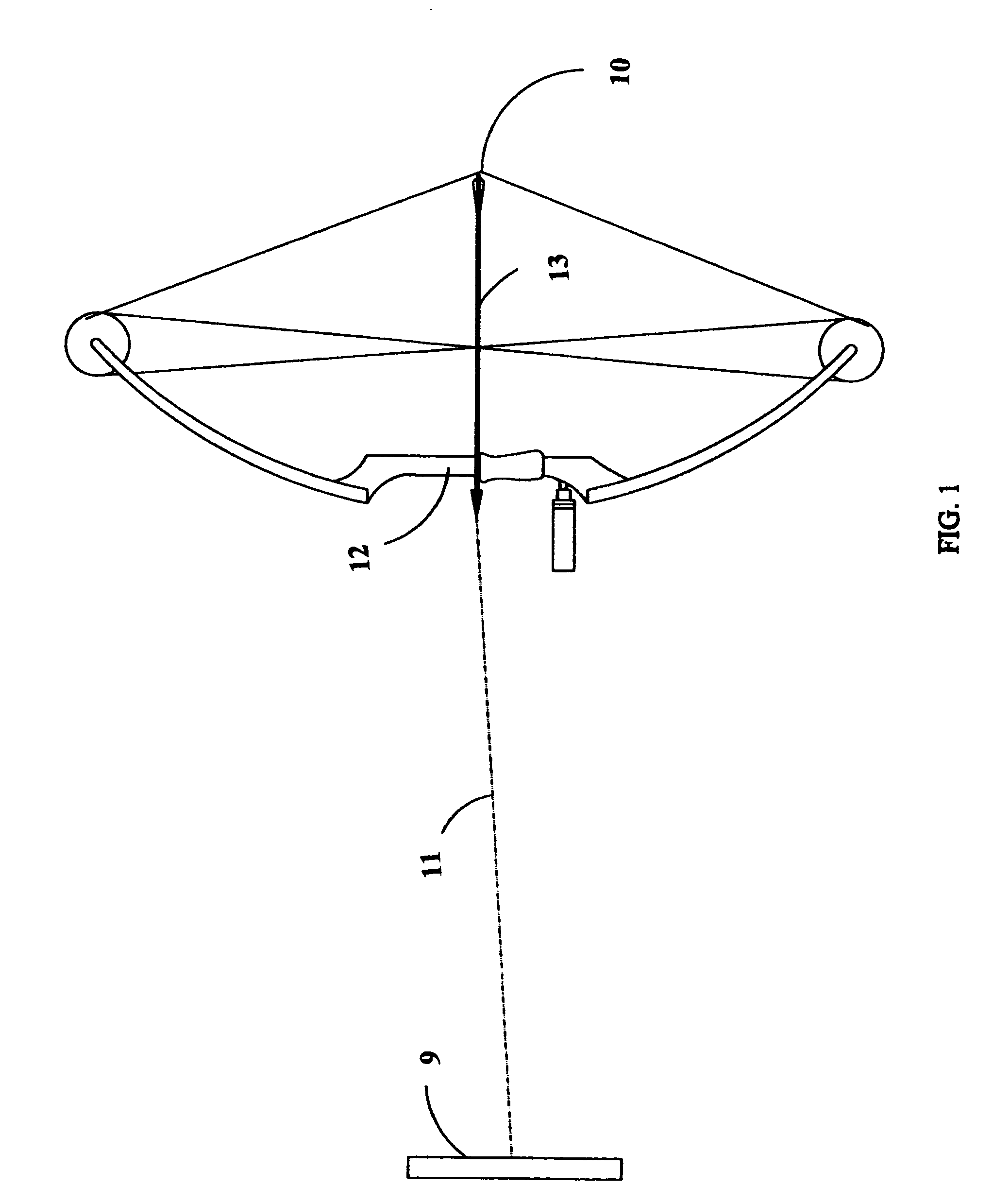
[0051]FIG. 1. There is shown a side view of bow 12 in full drawn position and furthermost rearward section of string 10, reference is made to FIG. 2 to better show the relationship of applied components.

[0052]The arrow trajectory 11 shows forward path taken buy arrow 13 t...


PUM


Abstract

An archery arrow including conventional components such as a tubular shaft, a pointed head attached to the forward end of the shaft, fletching on the rearward portion of the shaft and a nock at the rear end of the shaft. The arrow structure also includes an illuminated nock of the present invention and includes a battery/switch/collar/L.E.D-combined unit, which is held in place by a single anchor pin with the L.E.D. portion of the battery inside a conventional translucent or clear nock. The arrow shaft also uses a wooden dowel or other like material to create a backstop and cushion within the arrow shaft. This may also be permanently constructed as part of the arrow shaft during manufacturing. This helps disperse the load generated from the strings forward motion when released from the bow in a full drawn position between the end cap and the entire battery and switch assembly. Upon shooting the arrow from a longbow, compound, or crossbow, the switch contacts are forced into the “closed switch” position by the forward force generated along the axis of the arrow shaft. Therefore, energizing the L.E.D. light source to give off light through the translucent or clear nock. Once shot and activated it's a simple matter of removing the nock from the shaft pulling rearward on the battery while holding the nock in a stationary position to turn the LED off. With this configuration of components said lighted nock can be dislodged from the arrow shaft and still remain in the lighted position. This invention is also reusable by turning said nock off and reinserting the nock back into the arrow shaft and shooting again. I have also made and tested a working prototype.

Description

CROSS-REFERENCE TO RELATED APPLICATIONS[0001]I claim the benefits of the earlier filing date Jan. 23, 2003 of Provisional Patent Application No. 60 / 442,108.FEDERALLY SPONSORED RESEARCH[0002]Not ApplicableSEQUENCE LISTING OR PROGRAM[0003]Not ApplicableBACKGROUND OF THE INVENTION[0004]1. Field of Invention[0005]The field of endeavor that this invention pertains to is archery hunting, with the specific subject matter pertaining to arrows and more specifically to one part of the arrow, the nock or insert located at the rearward most part of the arrow.[0006]Most hunting is done during low light levels when game is most active in wilderness areas characterized by dense foliage and trees. On shooting archery arrows, there is extreme difficulty in visually tracking the flight of an arrow to its destination. The arrow may strike a hard object or become buried under brush or snow. Arrow performance is also affected by the weight of the arrow inasmuch as arrow velocity varies inversely with ar...

Claims


Application Information

Patent Timeline
IPC IPC(8): F21V33/00F42B12/36
CPCF21V33/008F42B12/362F21Y2101/02F21Y2115/10
Inventor DICARLO, JOSEPH L.
Owner DICARLO JOSEPH L
Why Eureka
Try Eureka