Apparatus and method for determining orientation parameters of an elongate object

a technology of elongation object and orientation parameter, which is applied in the direction of angle measurement, using reradiation, instruments, etc., can solve the problems of inability to determine the inclination of the pen independently with on-board equipment, inertial sensors suffer drift errors and accumulation errors,

Active Publication Date: 2006-04-04
ELECTRONICS SCRIPTING PRODS
View PDF41 Cites 163 Cited by
  • Summary
  • Abstract
  • Description
  • Claims
  • Application Information

AI Technical Summary

Problems solved by technology

Unfortunately, all of these methods are cumbersome and limiting to the user because the signals sent from the pen have to be received by external devices.
In other words, the pen cannot determine its inclination independently with on-board equipment.
Unfortunately, inertial sensors suffer from drift errors and accumulation errors that typically increase as time squared for accelerometers and linearly with time for gyroscopes.
Although Cho's teaching goes far to solve the problems, it still lacks the versatility, efficiency and accuracy to be employed in determining orientation parameters of writing devices and elongate objects in general.

Method used


Image

  • Apparatus and method for determining orientation parameters of an elongate object
  • Apparatus and method for determining orientation parameters of an elongate object
  • Apparatus and method for determining orientation parameters of an elongate object

Examples


Embodiment Construction

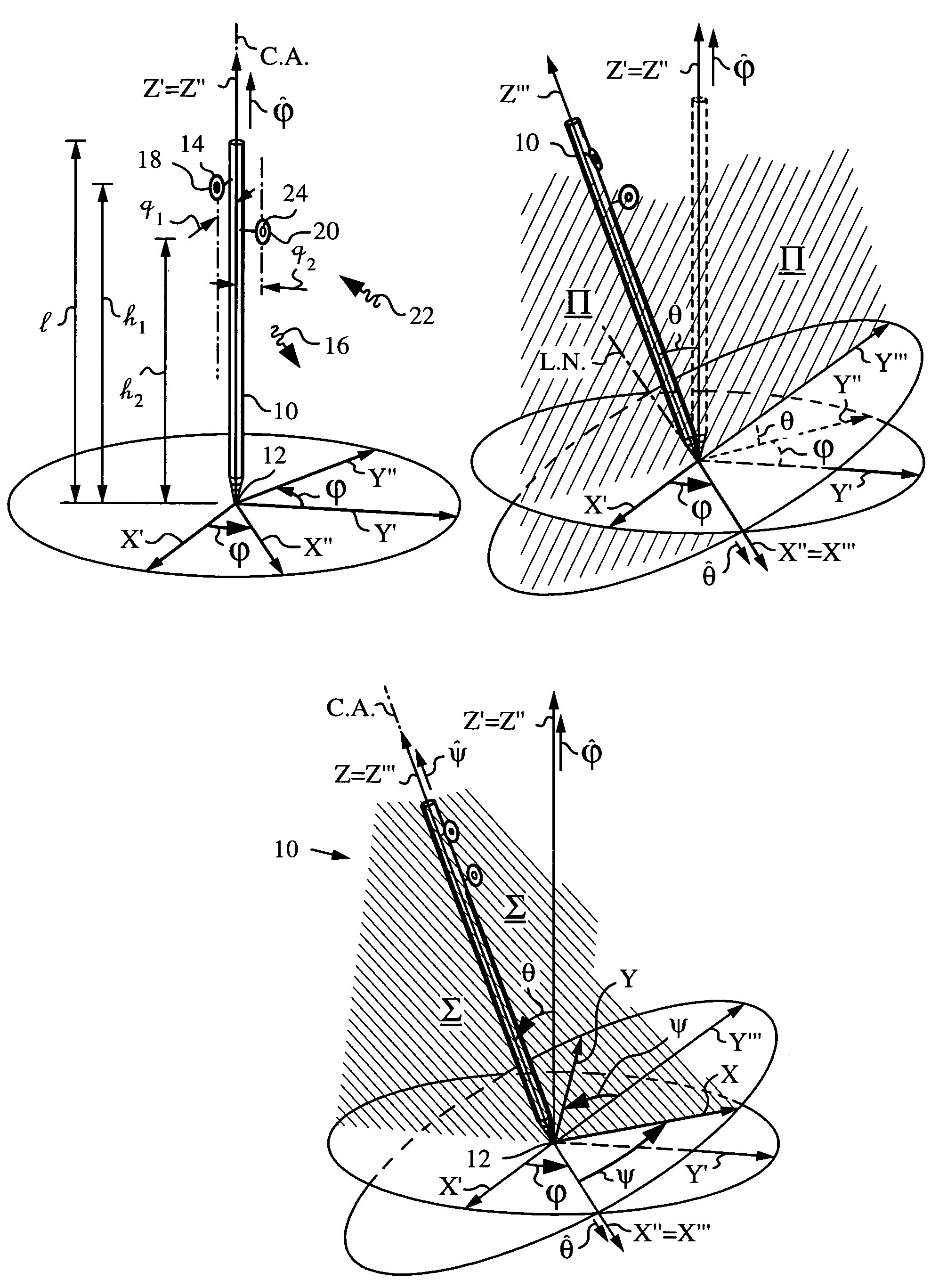
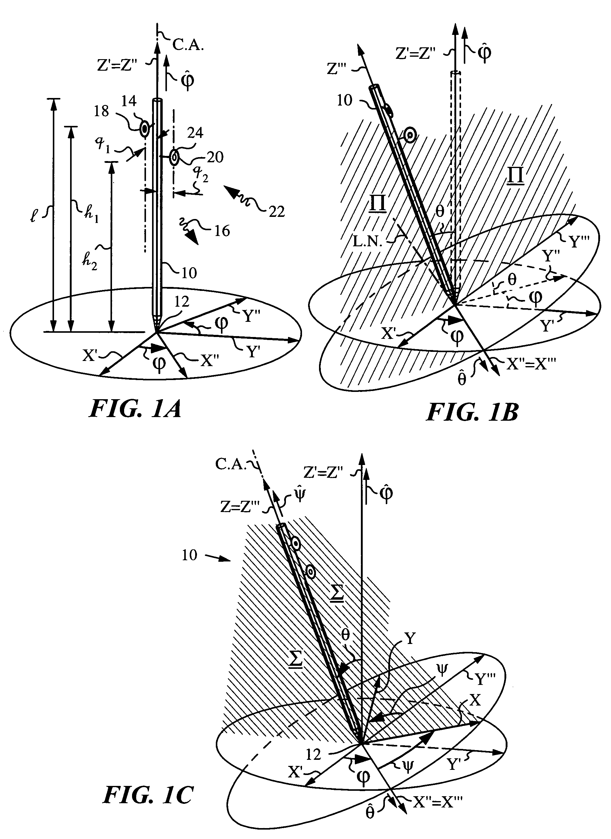
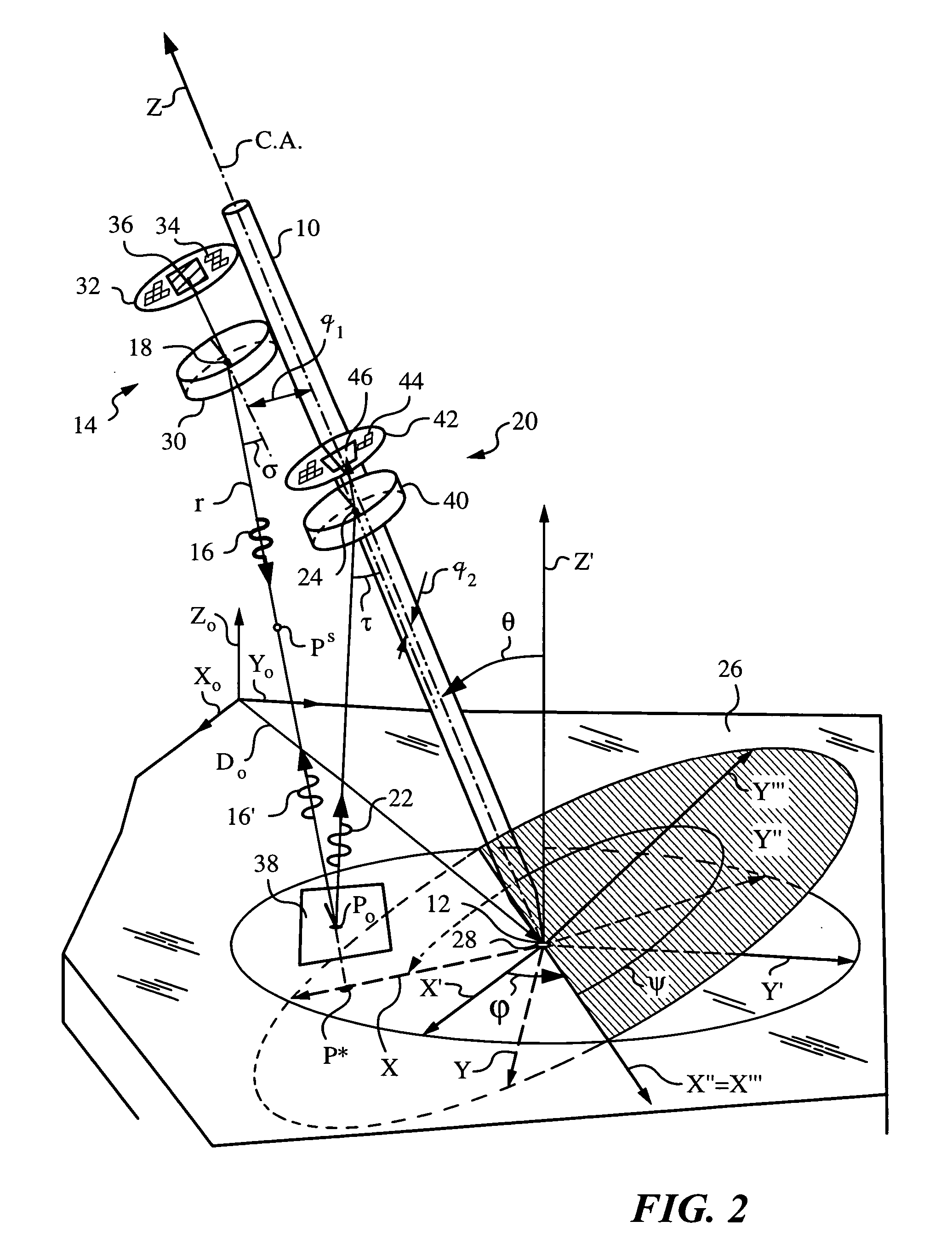
[0037]The present invention will be best understood by initially reviewing Euler rotations as used herein to describe the pose of an elongate object 10. The pose includes position and spatial orientation of elongate object 10. FIG. 1A illustrates object 10 of length l with a tip 12 at the origin of non-rotated object coordinates (X′,Y′,Z′). An axis of object 10, in the present embodiment a central axis or center axis denoted by C.A. is collinear with the Z′ axis. Axis C.A. passes through tip 12 and the origin of non-rotated object coordinates (X′,Y′,Z′). A projector 14 is mounted on object 10 for projecting a probe radiation 16 in a known pattern. Projector 14 projects radiation 16 from a first point of view 18 in plane (X′-Z′) at a height h1 at and an offset distance q1 from axis C.A. A detector 20 is mounted below projector 14 on object 10 for collecting or detecting a scattered portion 22 of probe radiation 16 returning to object 10. Detector detects scattered portion 22 at a sec...


PUM


Abstract

An apparatus and method employing principles of stereo vision for determining one or more orientation parameters and especially the second and third Euler angles θ, ψ of an elongate object whose tip is contacting a surface at a contact point. The apparatus has a projector mounted on the elongate object for illuminating the surface with a probe radiation in a known pattern from a first point of view and a detector mounted on the elongate object for detecting a scattered portion of the probe radiation returning from the surface to the elongate object from a second point of view. The orientation parameters are determined from a difference between the projected and detected probe radiation such as the difference between the shape of the feature produced by the projected probe radiation and the shape of the feature detected by the detector. The pattern of probe radiation is chosen to provide information for determination of the one or more orientation parameters and can include asymmetric patterns such as lines, ellipses, rectangles, polygons or the symmetric cases including circles, squares and regular polygons. To produce the patterns the projector can use a scanning arrangement or a structured light optic such as a holographic, diffractive, refractive or reflective element and any combinations thereof. The apparatus is suitable for determining the orientation of a jotting implement such as a pen, pencil or stylus.

Description

FIELD OF THE INVENTION[0001]The present invention relates generally to determining one or more orientation parameters of an elongate object whose tip is contacting a surface.BACKGROUND OF THE INVENTION[0002]When an object moves with respect to stationary references such as a ground plane, fixed points, lines or reference surfaces, knowledge of the object's inclination with respect to these references can be used to derive a variety of its parameters of motion. In fact, inclination of the object with respect to a reference is usually required for navigating the object or obtaining information about its trajectory. Over time, many useful coordinate systems and methods have been developed to parameterize the equations motion of such objects. For a theoretical background the reader is referred to textbooks on classical mechanics such as Goldstein et al., Classical Mechanics, 3rd Edition, Addison Wesley 2002. For general examples of object tracking and inclination measurements a few exam...

Claims


Application Information

Patent Timeline
Patent Type & Authority Patents(United States)
IPC IPC(8): G01B11/26G01C1/00
CPCG01B11/002G01B11/272G06F3/03545G06F3/0304G01S17/46G06F3/0354G06F3/03
Inventor ZHANG, GUANGHUA G.BUERMANN, DALE H.MANDELLA, MICHAEL J.GONZALEZ-BANOS, HECTOR H.CARL, STEWART R.
Owner ELECTRONICS SCRIPTING PRODS
Why Eureka
Try Eureka