Pattern inspection apparatus and method

a technology of pattern inspection and apparatus, applied in image enhancement, instruments, image data processing, etc., can solve the problems of detection errors, drop in detection sensitivity of small pattern defects, drop in detection sensitivity of defects

Active Publication Date: 2006-04-04
DAINIPPON SCREEN MTG CO LTD
View PDF7 Cites 12 Cited by
  • Summary
  • Abstract
  • Description
  • Claims
  • Application Information

AI Technical Summary

Benefits of technology

[0011]An object of the present invention is therefore to provide an apparatus and a method for pattern inspection using a comparative method employing a multivalued image so that detection errors due to image sampling error can be avoided and defects can be reliably detected.
[0019]This aspect of the invention selects the focus pixel in the reference image or inspection image having the least spatial variation in neighborhood pixel values as the tolerance pixel, selects the other focus pixel as the target pixel, and sets a tolerance range for the tolerance pixel. A pixel value difference is then calculated by comparing the target pixel with the tolerance pixel within the tolerance range, and compiles a difference map showing the differences between the inspection image and reference image based on the calculated difference values. The image for which the tolerance range is set for allowing error in the coincidence evaluation determining if the value of the focus pixel in the inspection image and the value of the focus pixel in the reference image match is thus changed as needed pixel by pixel according to spatial variation in the focus pixel neighborhood, thereby improving defect detection sensitivity and making it possible to avoid detection of pseudodefects due to image sampling error. More specifically, if there is a small pattern loss in the inspected object, the focus pixel of the inspection image has little spatial variation in the neighborhood pixel values and is selected as the tolerance pixel in that small pattern part, and a wide tolerance range does not result as it does with the prior art method. Small pattern loss in the inspected object can therefore be reliably detected.
[0023]With this aspect of the invention the focus pixel having less variance in pixel values in the neighborhood pixel group is selected from the focus pixels of the inspection image and reference image as the tolerance pixel, and the tolerance range is calculated therefor. It is therefore possible to improve defect detection sensitivity and to avoid false defect detection due to image sampling error.
[0025]When thus comprised the tolerance range is calculated according to the variation in pixel values in areas where there is great variation in the pixel values, such as at image edges. It is therefore possible to detect defects with good precision and to avoid false defect detection due to image sampling error.

Problems solved by technology

When this comparative method uses a multivalued image for pattern inspection, detection errors can occur due to error in the sampling position when the image is captured (referred to below as “image sampling error”).
More specifically, even if a difference between compared pixel values in the reference image and inspection image is detected, it is not known whether this difference is due to an actual defect or to the effects of this image sampling error, and parts that are not actually defects are falsely detected as defects.
This means that detection sensitivity to small pattern defects drops with the prior art method due to the pixel value range setting.
As a result, if the candidate defects are obtained by binary-digitizing the difference map generated from both inspections using the same threshold value Th, defect detection sensitivity drops in the second inspection because the value of the pixel difference is lower, and it becomes easy to miss defects.

Method used


Image

  • Pattern inspection apparatus and method
  • Pattern inspection apparatus and method
  • Pattern inspection apparatus and method

Examples


Embodiment Construction

[0044]Preferred embodiments of the present invention are described below with reference to the accompanying figures.

1. Overall Configuration of a Pattern Inspection Apparatus

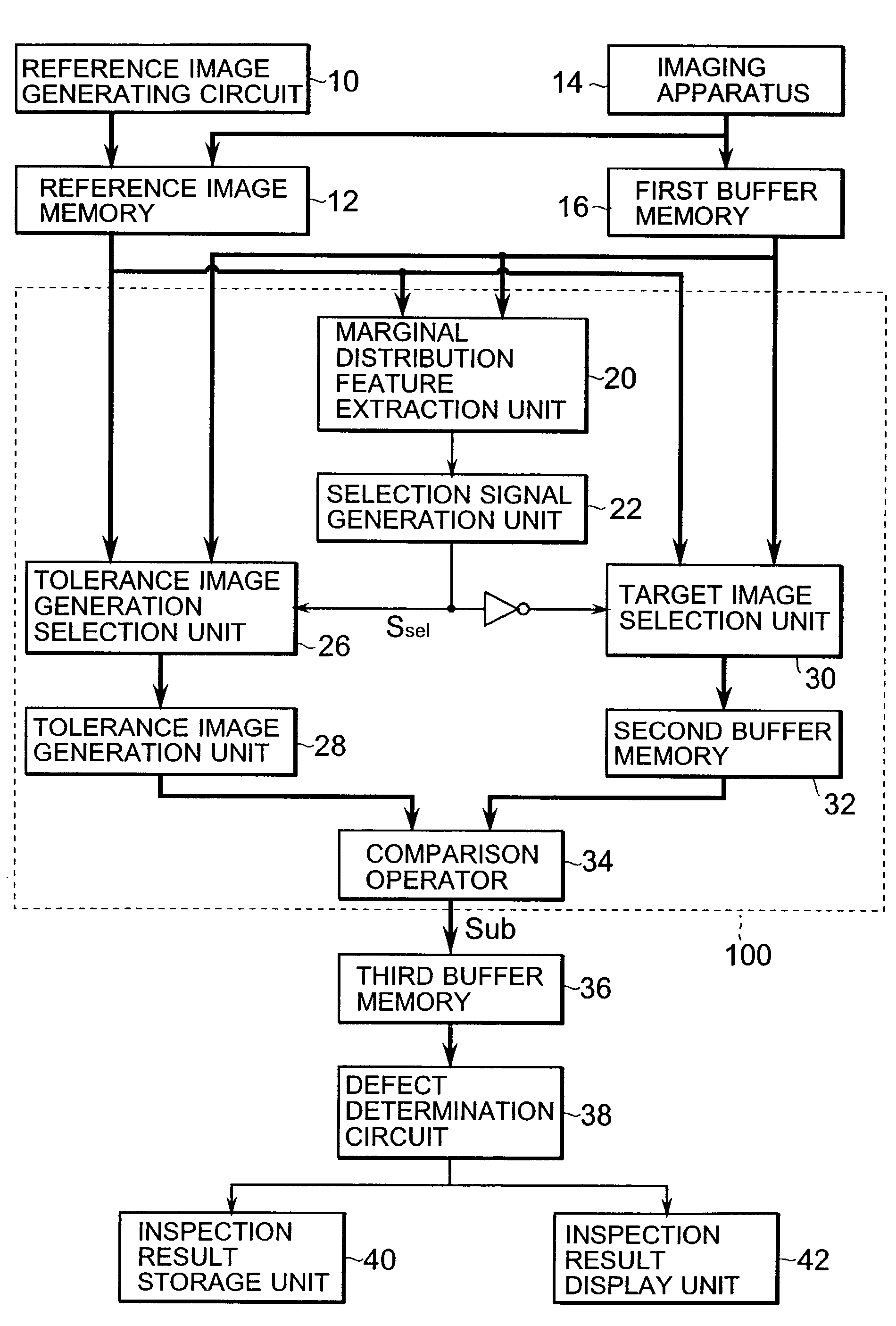
[0045]FIG. 1 is a block diagram showing the configuration of a pattern inspection apparatus according to a preferred embodiment of the present invention. This pattern inspection apparatus detects defects in an inspected object by comparing each pixel in an inspected object image and a reference image. The inspected object image is a multivalued image obtained by photographing an inspected object such as a printed wiring board or semiconductor wafer with a pattern formed on the surface thereof. The reference image is a multivalued image equivalent to an image of a good object of the same type as the inspected object. The reference image is an image used as the standard for comparing the inspected object image in order to detect defects in the inspected object, and can be generated by photographing a good object o...


PUM

PropertyMeasurementUnit
digital image defect detectionaaaaaaaaaa
widthaaaaaaaaaa
thresholdaaaaaaaaaa

Abstract

A marginal distribution feature extraction unit 20 sequentially focuses on each pixel in a reference image and the corresponding pixel in an inspection image, and computes a marginal distribution feature value indicative of the spatial variation in pixel values in the focus pixel neighborhood in both images. Based on this marginal distribution feature value, a tolerance image generation selection unit 26 sets a tolerance range for the reference image or inspection image focus pixel with the less spatial variation. A target image selection unit 30 selects the image comprising pixels from both images for which a tolerance range is not set as a target image. Referencing the set tolerance ranges, a comparison operator 34 compares each pixel in the target image and tolerance image, and outputs a difference Sub representing how far the pixel values of the target image are from the respective tolerance range. A defect determination circuit 38 then outputs data indicating the pixels corresponding to a defect based on a difference map containing these difference Sub values.

Description

BACKGROUND OF THE INVENTION[0001]1. Field of the Invention[0002]The present invention relates generally to a pattern inspection apparatus for inspecting a pattern and detecting defects appearing in the external shape of various inspected objects, and relates more specifically to a pattern inspection apparatus for inspecting patterns on high resolution printed wiring boards, lead frames, semiconductor wafers, and the like and photomasks therefor, and detecting minute defects therein.[0003]2. Description of the Related Art[0004]One method of inspecting patterns on high precision printed wiring boards, lead frames, semiconductor wafers, and the like and photomasks therefor is the comparative method. This method detects defects in an inspected object by comparing the values of positionally corresponding pixels (referred to below as simply “corresponding pixels”) in a reference image representing a good pattern with no defects and the inspection image representing the pattern on the insp...

Claims


Application Information

Patent Timeline
Patent Type & Authority Patents(United States)
IPC IPC(8): G06K9/68G01B11/24G01N21/956G06K9/62G06T1/00G06T7/00H05K3/00
CPCG01N21/95607G06K9/6255G06T7/001G06T2207/30148G06T2207/30141G06F18/28
Inventor SASA, YASUSHI
Owner DAINIPPON SCREEN MTG CO LTD
Why Eureka
Try Eureka