Method and apparatus for supplying auxiliary power to a bus coupled peripheral

a technology of auxiliary power and peripherals, which is applied in the direction of power supply for data processing, instruments, computing, etc., can solve the problems of limited current levels that can be supplied from a conventional usb bus, the total power drawn by the hub itself, and the limited number of downstream devices

Active Publication Date: 2006-04-04
INTELLECTUAL VENTURES II
View PDF11 Cites 53 Cited by
  • Summary
  • Abstract
  • Description
  • Claims
  • Application Information

AI Technical Summary

Benefits of technology

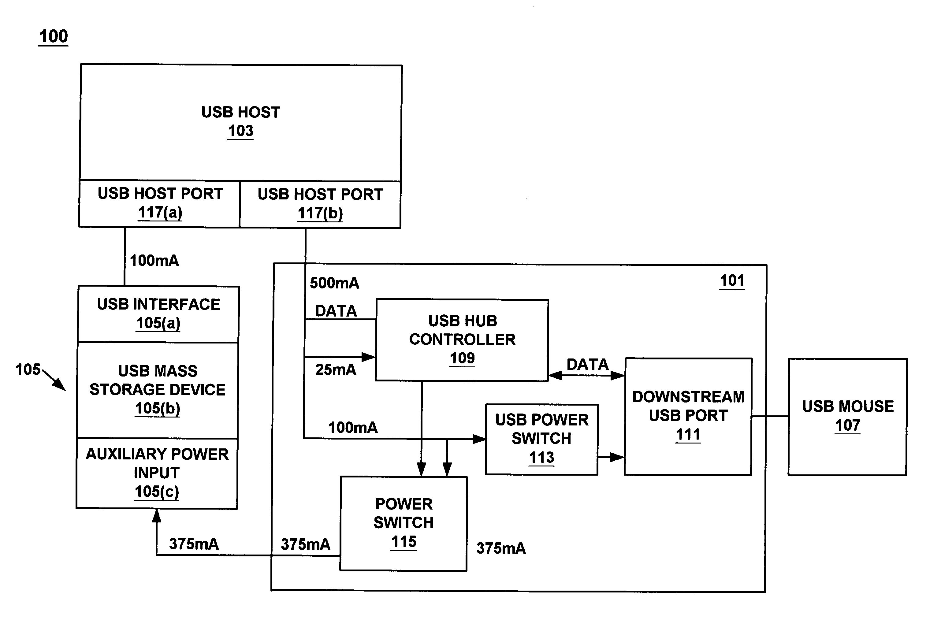
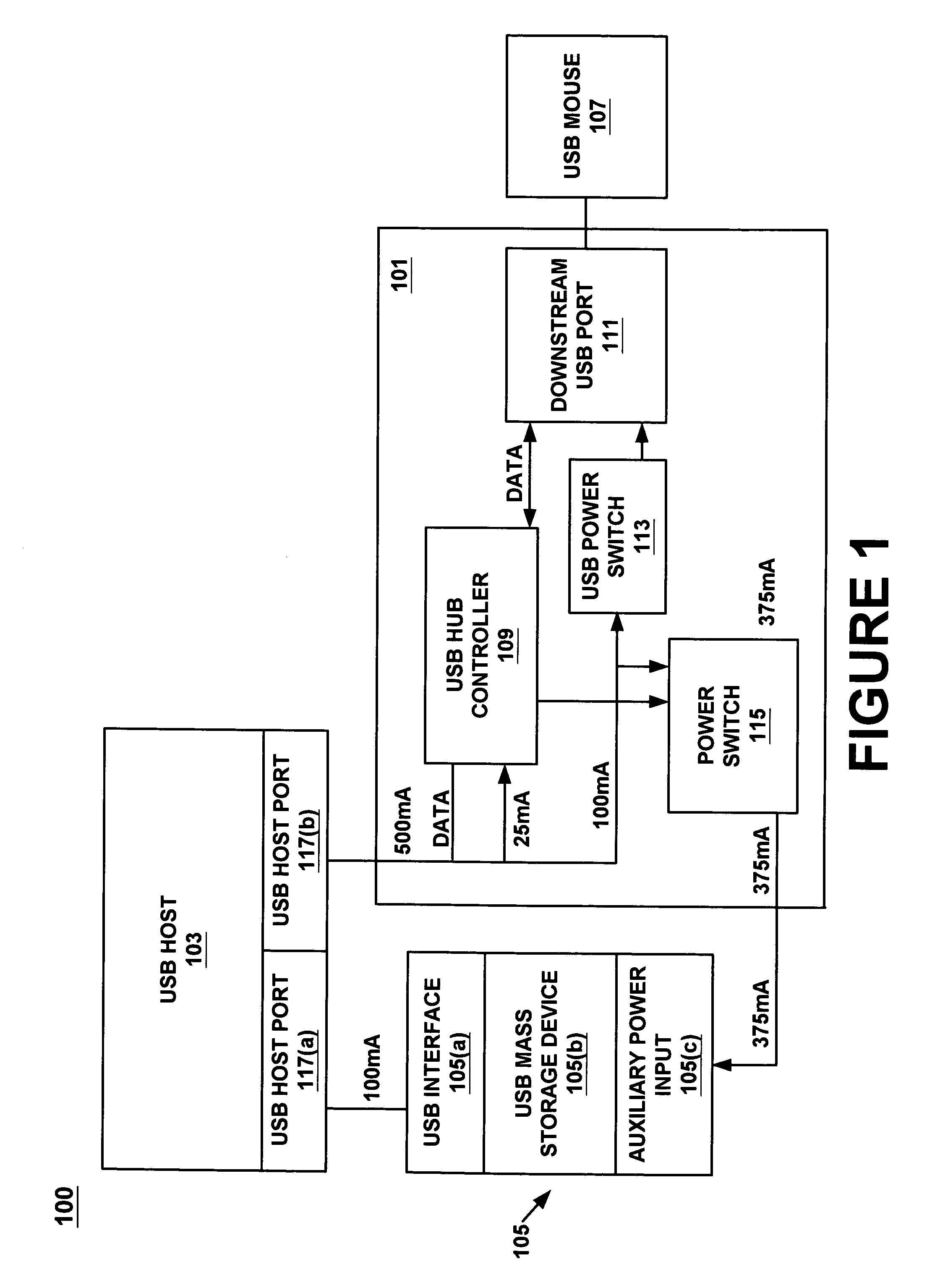
[0008]For instance, one embodiment of the present invention provides a method and apparatus for supplying auxiliary power to a peripheral thereby allowing the peripheral to be completely bus powered even though the peripheral requires more current than that supplied by a single communication port, e.g., a USB port. The method includes supplying power from a first USB port of a host device to an upstream USB port of a USB hub device, supplying power through a downstream USB port of said USB hub device for use by a downstream USB device, supplying auxiliary power through a power output port of said USB hub device for use by a peripheral device that is coupled to said power output port and supplying power from a second USB port of said host device to said peripheral device. The power received by the peripheral device is then sufficient for its op...

Problems solved by technology

This means that the total power drawn by the hub itself, together with all downstream devices is limited to 500 mA at the high end.
Because of this requirement, the limited levels of current that can be supplied from a conventional USB bus are not sufficient to power devices that require more than 500 mA of operating current.
However, 5 volt only CDRW and DVD-ROM drives are less common, as these drives typically require both 5 and 12 volts to operate.
A disadvantage of this conventional architecture is the typical requirement th...

Method used


Image

  • Method and apparatus for supplying auxiliary power to a bus coupled peripheral
  • Method and apparatus for supplying auxiliary power to a bus coupled peripheral
  • Method and apparatus for supplying auxiliary power to a bus coupled peripheral

Examples


Embodiment Construction

[0021]Reference will now be made in detail to the preferred embodiments of the invention, examples of which are illustrated in the accompanying drawings. While the invention will be described in conjunction with the preferred embodiments, it will be understood that they are not intended to limit the invention to these embodiments. On the contrary, the invention is intended to cover alternatives, modifications and equivalents, which may be included within the spirit and scope of the invention as defined by the appended claims. Furthermore, in the following detailed description of the present invention, numerous specific details are set forth in order to provide a thorough understanding of the present invention. However, it will be obvious to one of ordinary skill in the art that the present invention may be practiced without these specific details. In other instances, well known methods, procedures, components, and circuits have not been described in detail as not to unnecessarily ob...


PUM


Abstract

A method and apparatus for supplying auxiliary power to a peripheral is disclosed. The method includes supplying power from a first USB port of a host device to an input USB port of a USB hub device, supplying power through a downstream USB port of the USB hub device for use by a downstream USB device, supplying auxiliary power through a power output port of the USB hub device for use by a peripheral device that is coupled to an upstream port and supplying power from a second USB port of the host device to the peripheral device. The power received by the peripheral device is sufficient for its operation.

Description

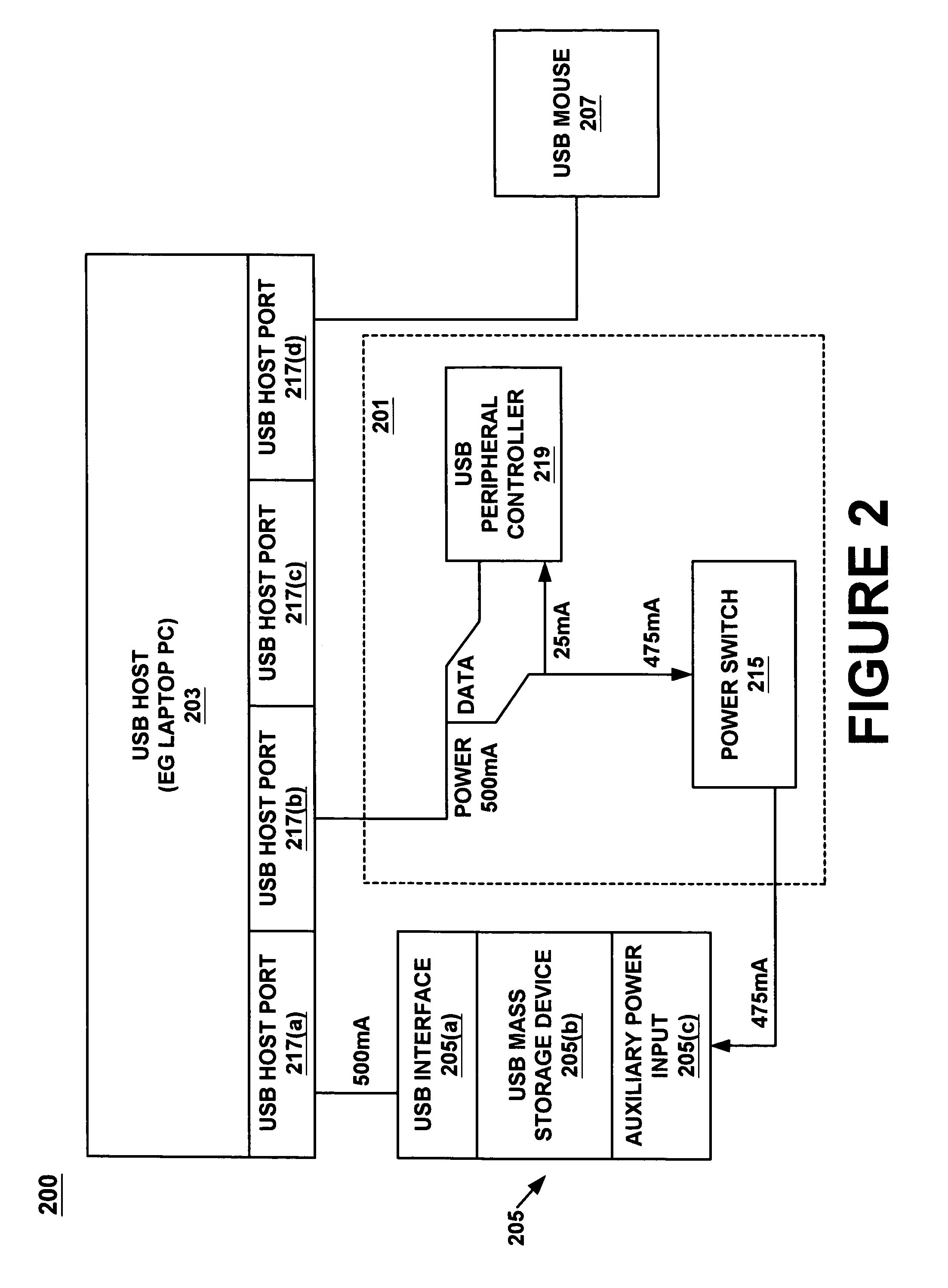
FIELD OF THE INVENTION[0001]Embodiments of the present invention relate generally to USB (Universal Serial Bus) peripherals. In particular, an embodiment of the present invention relates to a method and apparatus for increasing the power that is available to a USB peripheral.BACKGROUND OF THE INVENTION[0002]Peripherals may be connected to a host computer using a USB (Universal Serial Bus). Moreover, peripherals may be connected to a computer through a bus powered USB hub. Bus-powered USB hubs are “high power” USB devices. This means that the total power drawn by the hub itself, together with all downstream devices is limited to 500 mA at the high end.[0003]Many laptops have two USB (Universal Serial Bus) ports that may supply current to downstream sources. These USB ports are configured to each supply 500 mA of operating current to downstream devices. Most conventional mass storage devices require 0.5–1.0A of operating current for operation purposes. Because of this requirement, the...

Claims


Application Information

Patent Timeline
IPC IPC(8): G06F13/14
CPCG06F1/266
Inventor WRIGHT, DAVID G.CHANG, JEFF
Owner INTELLECTUAL VENTURES II
Why Eureka
Try Eureka