High efficiency two-stage dynamic classifier

US7028847B2Active Publication Date: 2006-04-18SCHENCK PROCESS LLC

Image

  • High efficiency two-stage dynamic classifier
  • High efficiency two-stage dynamic classifier
  • High efficiency two-stage dynamic classifier

Examples


Embodiment Construction

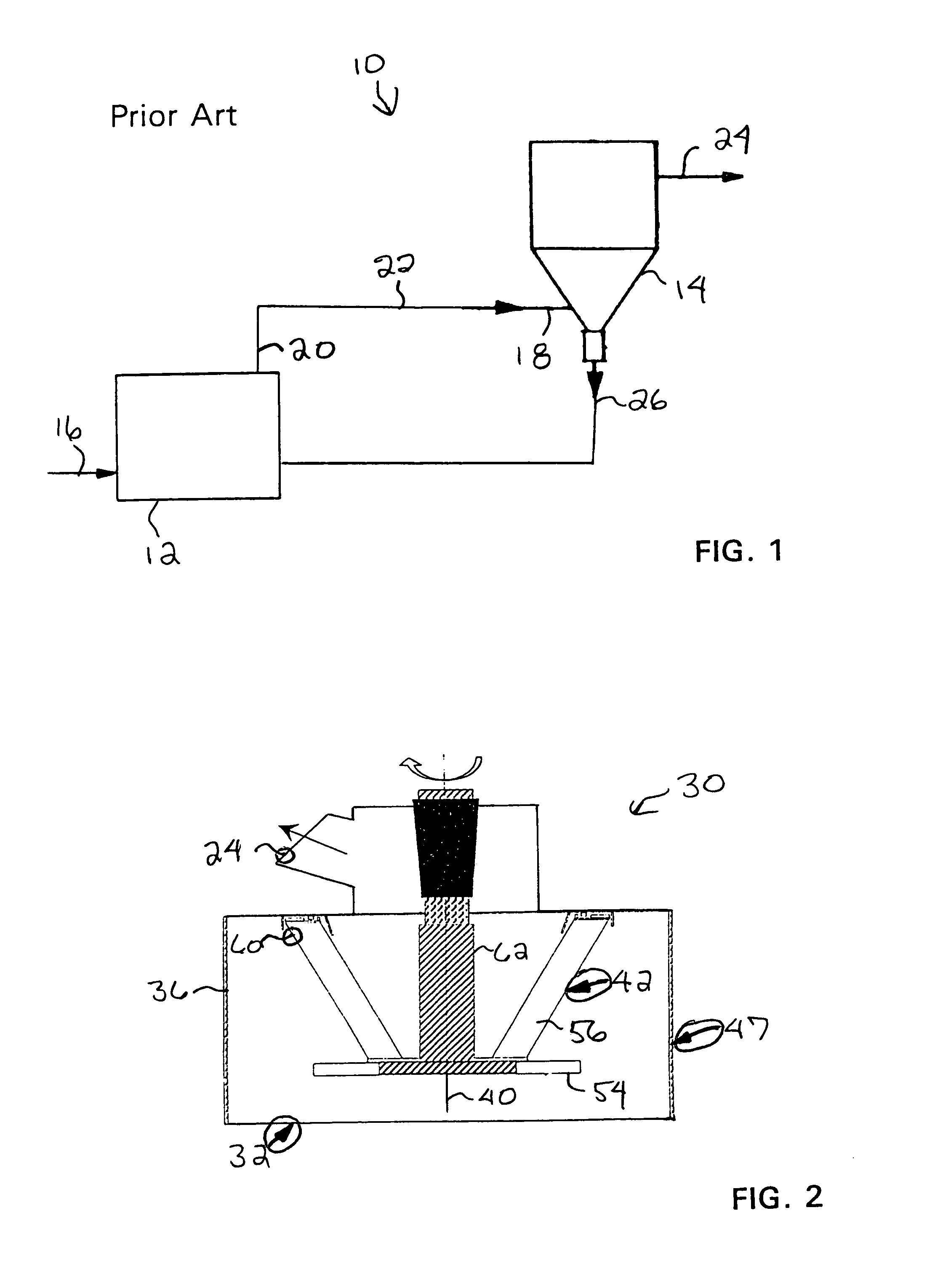
[0026]With reference to FIG. 1, there is illustrated therein a conventional separator system, generally designated by the reference numeral 10, which includes a grinding means 12 and a separator or classifier 14 which are interconnected in a closed circuit flow path.

[0027]The separator system 10 is designed to be operative both to grind material and to thereafter separate the ground material into a finished product which embodies particles that are of a predetermined size. To this end, the mode of operation, simply stated, is such that material which is to be ground is fed to the grinding means 12 wherein the material undergoes grinding. To this end, raw material in the required quantity and at the required rate is supplied from a suitable source of supply thereof (not shown) to the grinding means 12 by any suitable sort of transport means to the inlet 16 of the grinding means 12. After being ground in the grinding means 12, the material is fed in the form of feed material to the se...


PUM


Abstract

A two-stage dynamic classifier (30, 30′) for classifying a pulverized feed material (34, 34′, 38) entrained in an air flow (31) includes a vertically extending housing having a lower feed material inlet (18), an upper feed material outlet (24), a processing section (47, 47′) disposed between the feed material inlet and the feed material outlet, and a lower tailings discharge (26). A classifier conditioner (32) is disposed in a lower portion of the processing section and a turbine classifier (42, 44) is disposed in an upper portion of the processing section.

Description

BACKGROUND OF THE INVENTION[0001]This invention relates to particulate matter classifiers. More particularly, the present invention relates to apparatus for separating particles of a certain fineness from larger particles.[0002]It has long been known in the prior art to provide apparatus for purposes of effecting the grinding or pulverizing of certain materials. More specifically, the prior art is replete with examples of various types of apparatus that have been used to effect such grinding of a multiplicity of materials. In this regard, in many instances discernible differences of a structural nature can be found to exist between individual ones of the aforesaid apparatus. The existence of such differences is, in turn, attributable for the most part to the diverse functional requirements that are associated with the specific applications in which such apparatus are designed to be employed. For instance, in the selection of the particular type of apparatus that is to be utilized fo...

Claims


Application Information

Patent Timeline
18 Apr 2006
Publication
US7028847B2
IPC
B07B9/00; B07B4/00; B02C15/00; B07B7/083
CPC
B07B7/083; B02C2015/002
Inventors
CHEN, MICHAEL M.; CHEN, JIANRONG