
Organizer including resilient retaining members

a technology of retaining members and organizers, applied in the field of organizers, can solve the problems of reducing the safety and efficiency of persons or activities associated with the environment, limited space in the environment to store such items, and system difficulties in accommodating a large number of items, so as to achieve the effect of easy reconfigurability, easy coupling of retaining members, and easy increase or decrease of the housing of the organizer

Inactive Publication Date: 2006-04-18
MASTER MFG
View PDF24 Cites 29 Cited by
  • Summary
  • Abstract
  • Description
  • Claims
  • Application Information

AI Technical Summary

Benefits of technology

[0005]There is a need for an organizer that uses resilient retaining members and is easily reconfigurable, e.g., the number of retaining members coupled to the housing of the organizer can be easily increased or decreased. Further, there is a need for an easily reconfigurable organizer with retaining members having coupling segments that tend to inhibit inadvertent removal of a retaining member when a force that is generally normal to the elongated extent of the housing is applied to the retaining member.

Problems solved by technology

Unorganized distribution of these items in an environment may decrease the safety and efficiency of the persons or activities associated with that environment.
Additionally, there may be limited space in an environment to store such items.
However, such systems may have difficulty accommodating a large number of items.
Further, users may not be able to remove easily items from such systems once secured.
However, reconfiguration of these systems by removing or adding loops may not be easily accomplished as the loops are designed to be fixedly retained by the frame by a hooked tab.
In other cases, the tab used to couple the loop to the frame may not be sufficient to retain the loop in the frame when a force that is generally normal to the elongated extent of the frame is applied to the loop.

Method used


Image

  • Organizer including resilient retaining members
  • Organizer including resilient retaining members
  • Organizer including resilient retaining members

Examples


Embodiment Construction

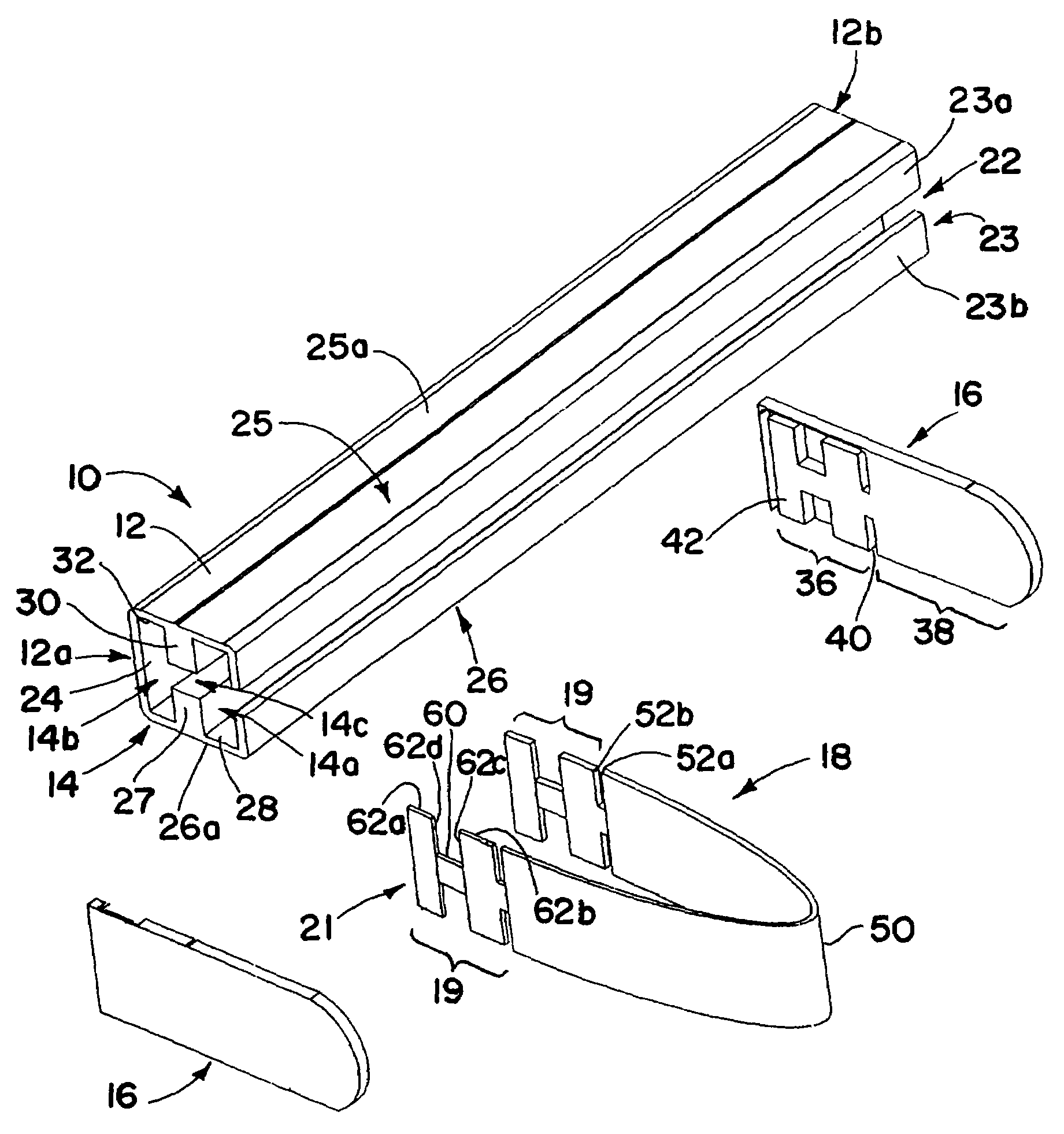
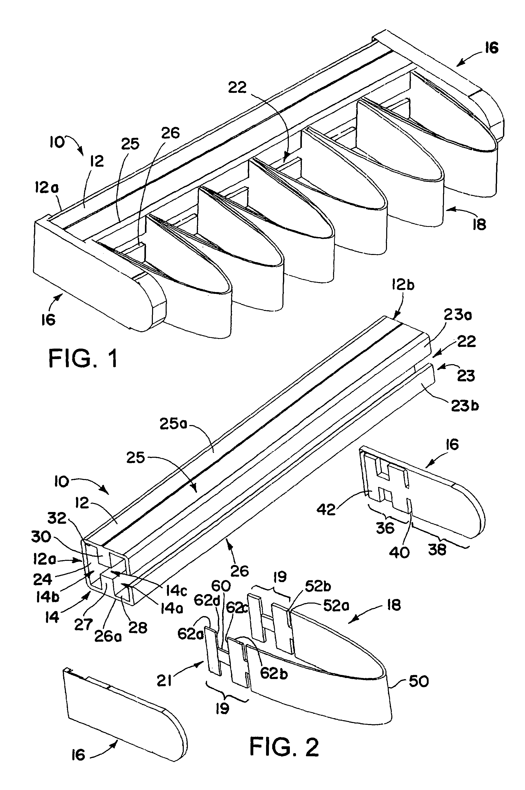
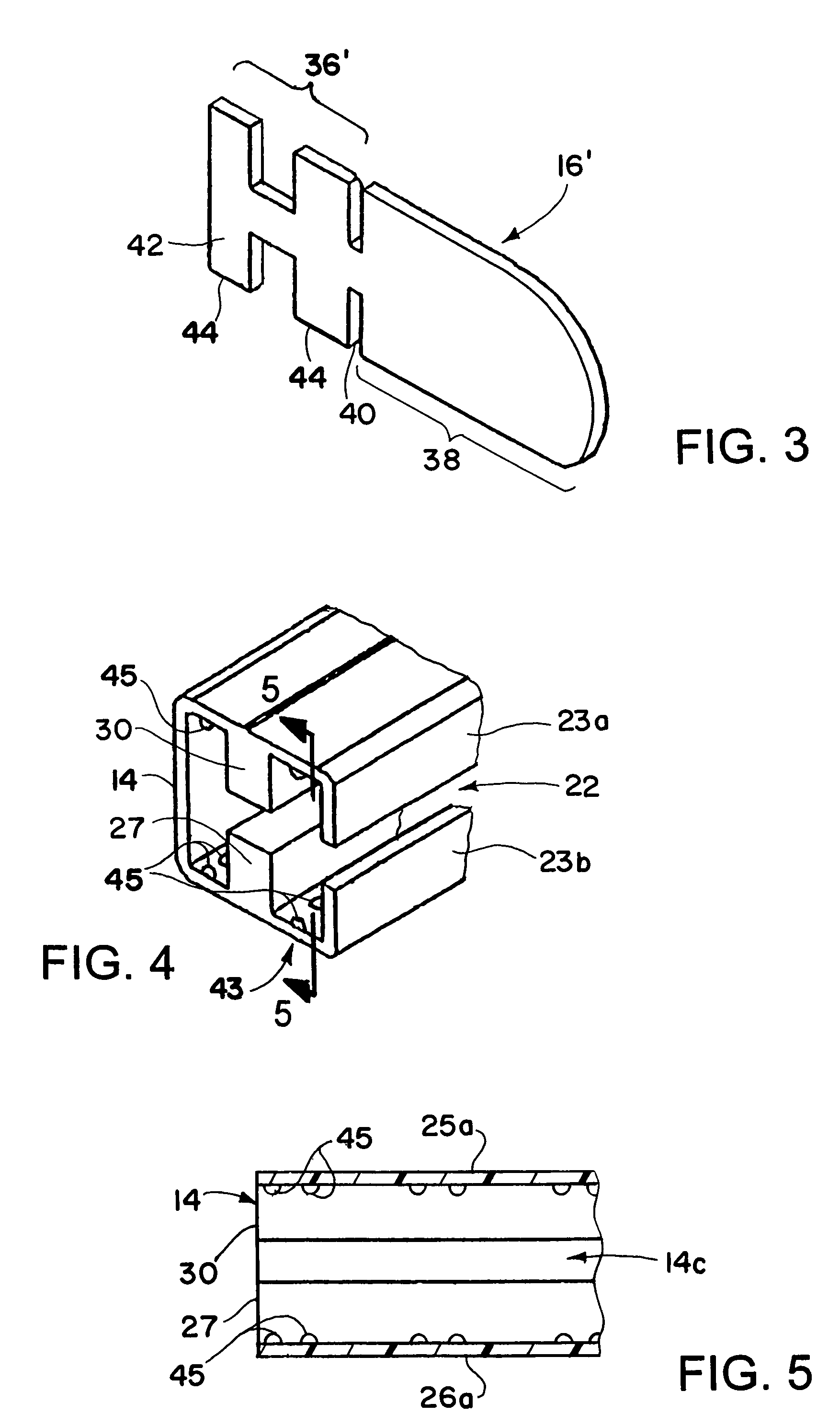
[0020]With reference to FIGS. 1–2, the invention is an organizer 10 that includes a housing 12 having a channel 14, channel end stops 16 and a plurality of strip-like retaining members 18 that are bent to form loops coupled to the housing operable to secure an item placed between adjacent retaining members 18. The retaining members 18 are coupled to the housing 12 with a hookless coupling segment 19 that inhibits inadvertent removal, but allows the organizer to be reconfigured easily. For example, ends 21 of a retaining member 18 can be pressed toward each other, slipped through a slot 22 in the front wall 23 of the housing 12 into the channel 14 and then rotated to an orientation generally filling a cross sectional slice of the channel for retention of the retaining member ends therein. The bending force, on the retaining members then may be released, and the cooperation between the ends 21 and the housing walls at the channel 14 holds the retaining member to the housing. In this w...


PUM


Abstract

An organizer (10) that includes a housing (12) having a first end (12a), a second end (12b), and a channel (14) extending along at least a portion of the housing (12) between the first end (12a) and the second end (12b). A plurality of retaining members (18) are coupled to the housing (12) using the channel (14). Each retaining member (18) exerts a retaining force upon one or more adjacent retaining members (18). The organizer (10) retains an item placed between adjacent retaining members (18) using the retaining force. The retaining members (18) include a hookless coupling segment (19) for coupling the retaining members (18) to the housing. The housing (12) includes at least one divider (27, 30) along at least a portion of the channel (14) to separate the channel (14) into at least two areas (14a, 14b and 14c).

Description

FIELD OF THE INVENTION[0001]The present invention generally relates to organizers, and, more particularly, to an organizer including resilient retaining members.BACKGROUND OF THE INVENTION[0002]People use various tools, objects, or other items to perform activities in an environment. Unorganized distribution of these items in an environment may decrease the safety and efficiency of the persons or activities associated with that environment. Additionally, there may be limited space in an environment to store such items.[0003]Persons performing these activities and inhabiting these environments may desire to organize and secure items in order to increase safety, efficiency and more effectively use the available space according to their needs. A known organization technique allows persons to place loose items in a clip affixed to an upright surface. However, such systems may have difficulty accommodating a large number of items. Further, users may not be able to remove easily items fro...

Claims


Application Information

Patent Timeline
IPC IPC(8): A47F5/08A47F7/00
CPCA47B65/00A47B81/068B25H3/04A47F7/0028A47L13/512A47F5/0846A47B81/005A47F7/0035
Inventor LONDRICO, PHILIP
Owner MASTER MFG
Learn More