[0009]The invention is accomplished to solve the aforementioned problem. Accordingly, an object of the invention is to provide a sheet feeder enabled to alleviate a difference in sheet-mounting-
surface level between a sheet mounting surface of the sheet tray and that of the sheet mounting portion of a sheet feeder body in the connection portion, in which the sheet tray and the sheet mounting portion are connected to each other, and to provide a sheet tray having such a sheet tray body.
[0011]According to the first sheet feeder of the invention, as described above, the difference in sheet-mounting-
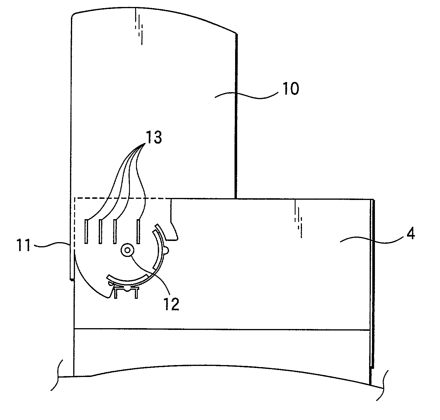
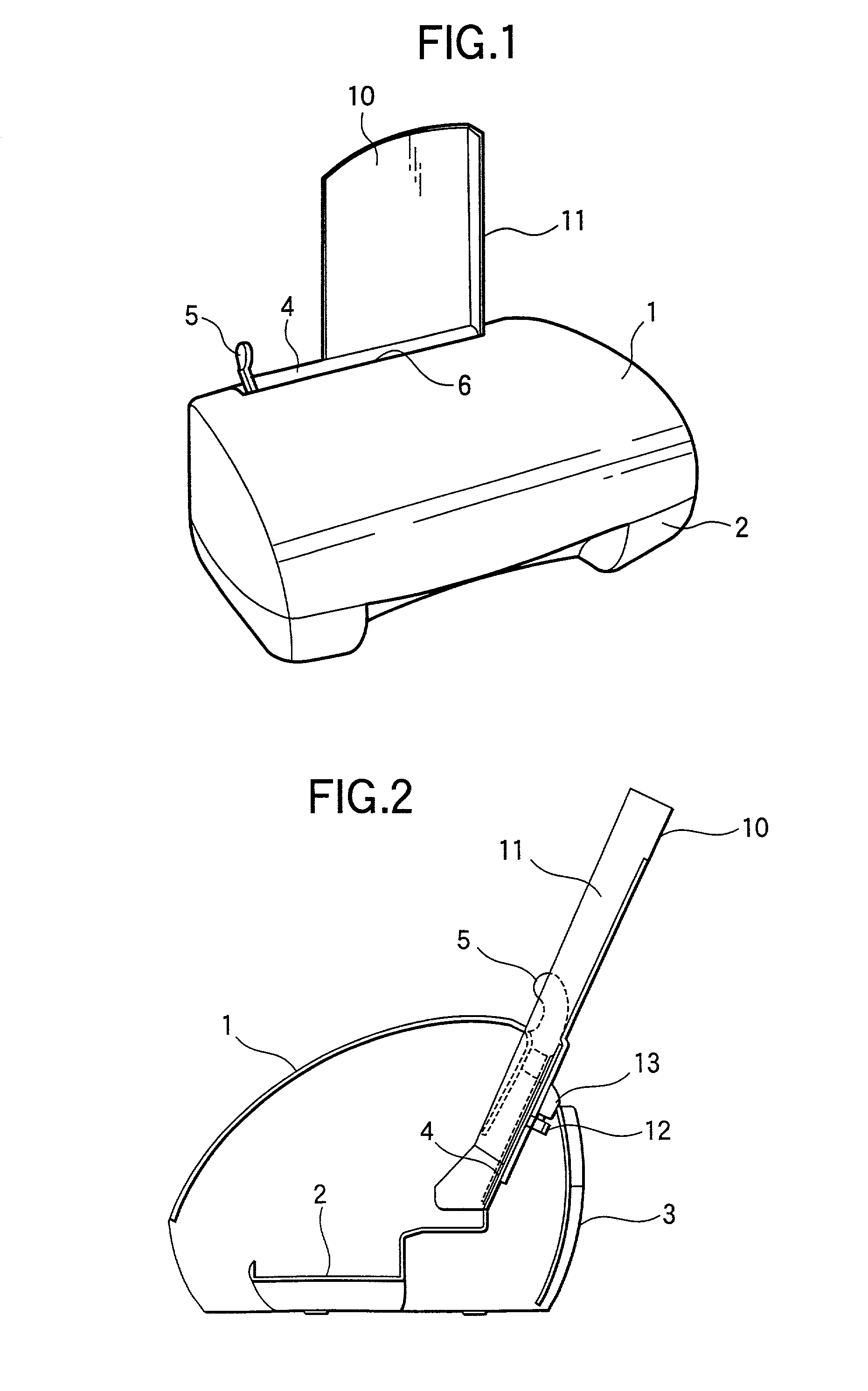
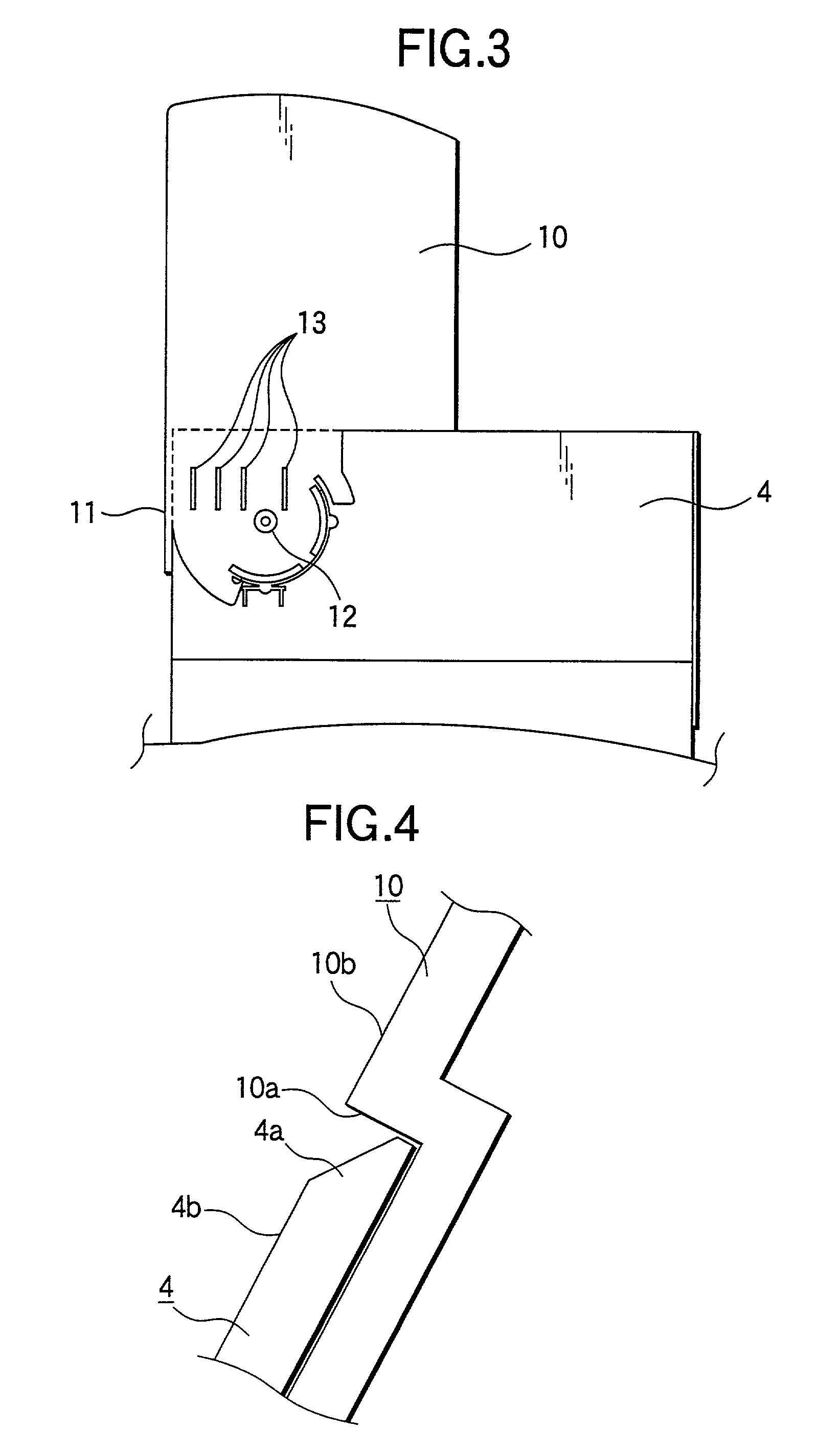
surface level between the sheet mounting surface of the sheet tray body and that of the sheet feeder body at the time of using the sheet tray body is alleviated by providing the step-like part in the sheet tray body in such a way as to be placed in the connection portion, in which the upper edge part of the sheet mounting portion of the sheet feeder body and the sheet tray body are connected to each other, when the sheet tray body is used. This mitigates the inconvenience that a sheet of paper is caught by the step-like part during paper feeding. Moreover, the sheet tray body is easily placed in a position, in which the sheet tray body is enabled so that the difference in sheet-mounting-
surface level between the sheet mounting surface of the sheet tray body and that of the sheet feeder body at the time of using the sheet tray body is alleviated, by providing the thrusting member, which is operative to frontwardly push the sheet tray body when the sheet tray body is used, in the sheet tray body. Incidentally, the sheet tray body is disposed in such a way as to be able to turn around the shaft provided in such a manner as to be nearly perpendicular to the sheet mounting surface thereof. Consequently, the sheet tray body is easily drawn out when the sheet tray body is used, and accommodated when the sheet tray body is not used, by laterally turning the sheet tray body.
[0013]According to the second sheet feeder of the invention, as described above, an abutting rib serving as the thrusting member for frontwardly pushing the sheet tray body by abutting against the sheet feeder body with turning the sheet tray body is provided on the rear surface of the sheet tray body in such a manner as to be integral with the sheet tray body. Thus, the second sheet feeder has an advantageous effect in that the number of components and the number of man-hours needed for fabricating the sheet feeder remain unincreased even when the abutting rib serving as the thrusting member is added to the sheet feeder.
[0015]According to the third sheet feeder of the invention, as described above, the difference in sheet-mounting-surface level between the sheet mounting surface of the sheet tray body and that of the sheet feeder body at the time of using the sheet tray body is alleviated by forming the upper edge part of the sheet mounting portion of the sheet feeder body in such a way as to have a tapered shape. Consequently, the difference in sheet-mounting-surface level between the sheet mounting surface of the sheet tray body and that of the sheet feeder body at the time of using the sheet tray body is more effectively alleviated by utilizing both the step-like part of the sheet tray body of the first sheet feeder of the invention and the tapered upper edge part of the sheet mounting portion of the sheet feeder body. The third sheet feeder more effectively mitigates the inconvenience that a sheet of paper is caught by the step-like part during paper feeding.
[0017]According to this sheet tray of the invention, as described above, the difference in sheet-mounting-surface level between the sheet mounting surface of the sheet tray body and that of the sheet feeder body at the time of using the sheet tray body is alleviated by providing the step-like part in the sheet tray body in such a way as to be placed in the connection portion, in which the upper edge part of the sheet mounting portion of the sheet feeder body and the sheet tray body are connected to each other, when the sheet tray body is used. This sheet tray mitigates the inconvenience that a sheet of paper is caught by the step-like part during paper feeding. Moreover, the sheet tray body is easily placed in a position, in which the sheet tray body is enabled so that the difference in sheet-mounting-surface level between the sheet mounting surface of the sheet tray body and that of the sheet feeder body at the time of using the sheet tray body is alleviated, by providing the thrusting member, which is operative to frontwardly push the sheet tray body when the sheet tray body is used, in the sheet tray body. Incidentally, the sheet tray body is disposed in such a way as to be able to turn around the shaft provided in such a manner as to be nearly perpendicular to the sheet mounting surface thereof. Consequently, the sheet tray body is easily drawn out when the sheet tray body is used, and accommodated when the sheet tray body is not used, by laterally turning the sheet tray body.
[0019]According to the fourth sheet feeder of the invention, as described above, the difference in sheet-mounting-surface level between the sheet mounting surface of the sheet tray body and that of the sheet feeder body at the time of using the sheet tray body is alleviated by providing the step-like part in the sheet tray body in such a way as to be placed in the connection portion, in which the upper edge part of the sheet mounting portion of the sheet feeder body and the sheet tray body are connected to each other, when the sheet tray body is used. The fourth sheet feeder mitigates the inconvenience that a sheet of paper is caught by the step-like part during paper feeding. Moreover, the sheet tray body is easily placed in a position, in which the sheet tray body is enabled so that the difference in sheet-mounting-surface level between the sheet mounting surface of the sheet tray body and that of the sheet feeder body at the time of using the sheet tray body is alleviated, by providing the thrusting member, which is used for frontwardly pushing the sheet tray body when the sheet tray body is used, in the sheet tray body. Incidentally, the sheet tray body is disposed in such a way as to be able to turn around the shaft provided in such a manner as to be nearly perpendicular to the sheet mounting surface thereof. Consequently, the sheet tray body is easily drawn out when the sheet tray body is used, and accommodated when the sheet tray body is not used, by laterally turning the sheet tray body.

