Support structure for a portable air compressor

a portable, support structure technology, applied in the direction of positive displacement liquid engine, pump components, piston pumps, etc., can solve the problems of affecting the service life of the air compressor, the assembly can tip over when pushed or pulled by the handle, and the damage of items which extend beyond the perimeter of the fram

Inactive Publication Date: 2006-04-18
BLACK & DECKER INC
View PDF55 Cites 24 Cited by
  • Summary
  • Abstract
  • Description
  • Claims
  • Application Information

AI Technical Summary

Benefits of technology

[0008]In another preferred embodiment, a support structure for a portable air compressor includes a frame having a pair of approximately parallel side sections and a support plate horizontally disposed between the side sections. A plurality of components are connected to the support plate including an engine, a compressor and a fluid pressure tank. An axle is slidably disposed through a lower tubular portion of both side sections, the axle having distal ends operably forming opposed outer planar envelopes of the portable air compressor. An instrument support panel is connectably disposed on the frame and positioned adjacent to a select one of the outer planar envelopes. A plurality of instruments including an engine on / off switch, at least one pressure gage, at least one quick-disconnect fitting and at least one unloader valve are each mounted on the instrument support panel such that each of the instruments and the instrument support plate are completely disposed within one of the selected outer planar envelopes.

Problems solved by technology

Several drawbacks exist for common portable air compressor assemblies.
The first drawback is that the component parts of the air compressor assembly, typically items that include the muffler from a gasoline engine and the air filter for the engine, and the cooling head for the compressor, are often arranged outside of the structural envelope of the frame supporting the air compressor assembly.
Exposed components are susceptible to damage.
Another disadvantage of known portable air compressor assemblies is the tendency of the assembly to tip over when pushed or pulled by the handle.
When an air compressor assembly flips over, damage to those items which extend beyond the perimeter of the frame can occur and fuel spillage can also occur.

Method used


Image

  • Support structure for a portable air compressor
  • Support structure for a portable air compressor
  • Support structure for a portable air compressor

Examples


Embodiment Construction

[0023]The following description of the preferred embodiments is merely exemplary in nature and is in no way intended to limit the invention, its application, or uses.

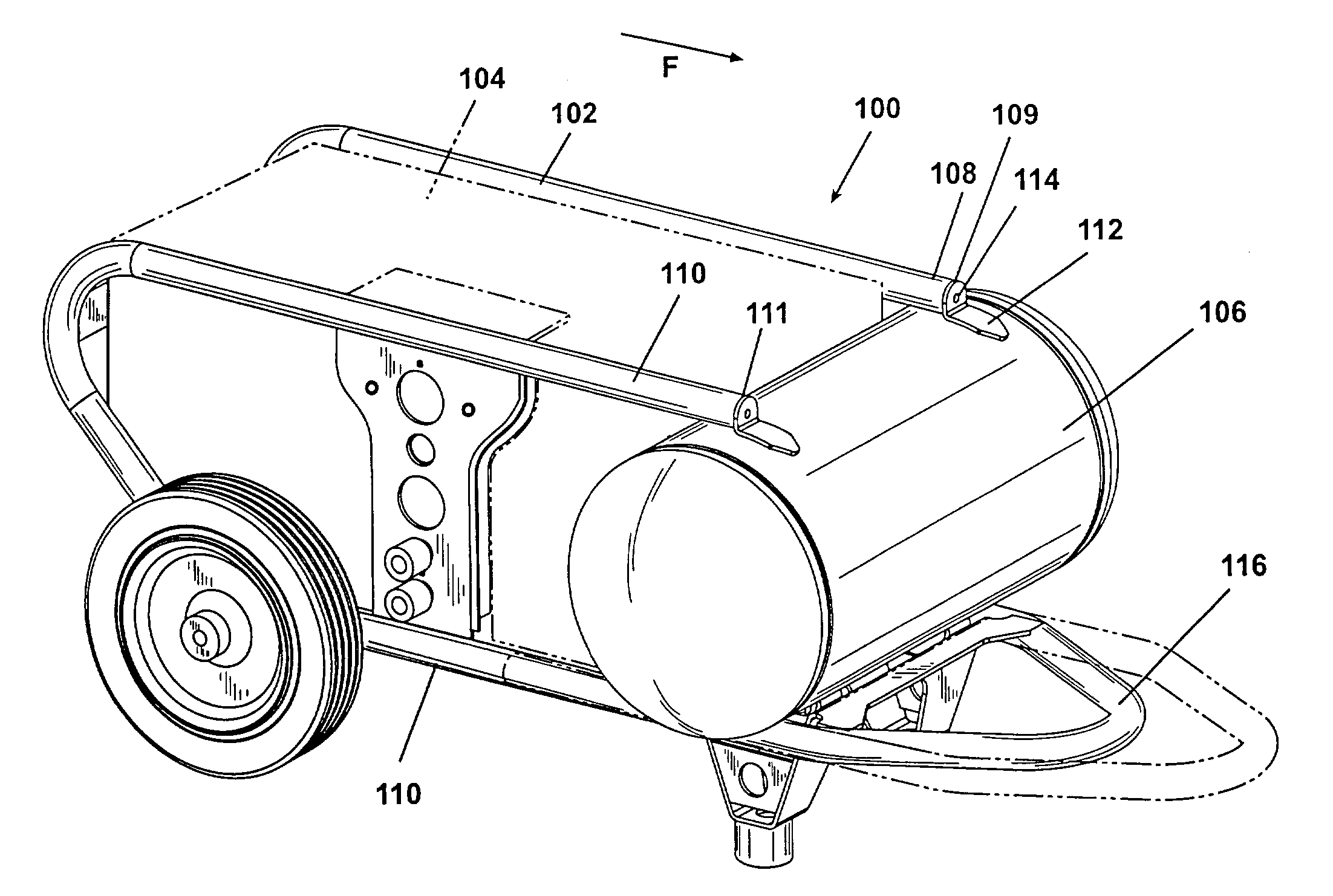
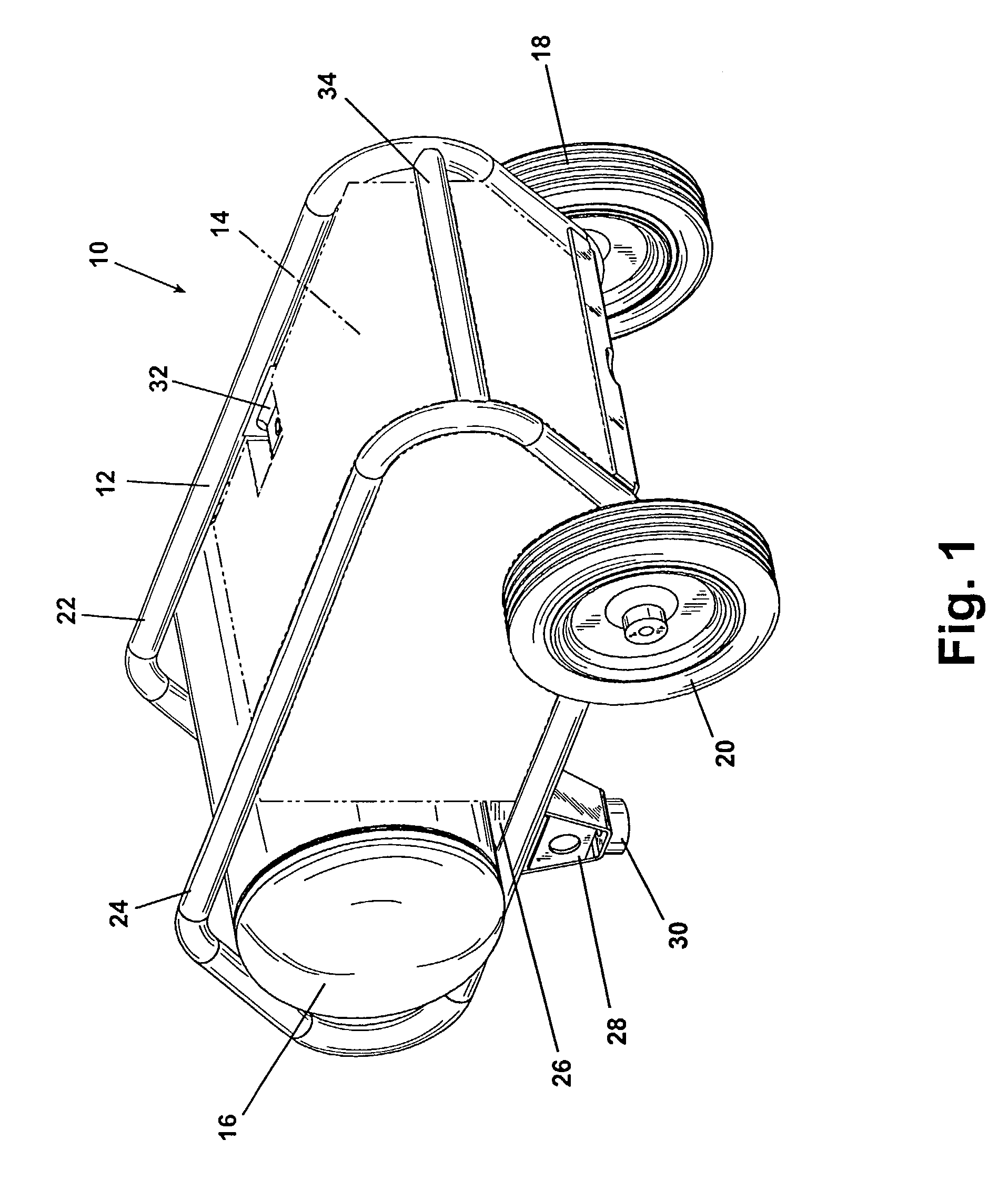
[0024]FIG. 1 shows an air compressor assembly 10 according to a preferred embodiment of the present invention. The air compressor assembly 10 includes a frame 12, a component group 14, and a fluid pressure tank 16. A first wheel 18 and a second wheel 20 are rotatably supported from the frame 12 at an aft end of the air compressor assembly 10. The frame 12 includes a first side 22 and a second side 24. The first side 22 and the second side 24 are generally tubular shaped frame members generally formed in a parallelogram configuration having rounded corners. A support plate 26 is provided at a lower portion of the frame 12 and is mechanically joined to the first side 22 and the second side 24, respectively. A pair of support feet 28 (only one is visible in this view) are mechanically joined to a forward end of the frame 1...


PUM


Abstract

A portable air compressor assembly includes a tubular frame having a pair of parallelogram shaped side sections. A support plate is connected between the side sections and horizontally positioned in a compressor normal operating position. A plurality of operating components connect to the support plate. A fluid pressure tank is supported perpendicular to the side sections and forward of the operating components. The frame envelopes the operating components' outer perimeter and angularly extends to a stop point rearward of the operating components. When tipped rearward to the stop point, the compressor assembly returns by gravity to the compressor normal operating position. An instrument and connector panel including an engine on/off switch is mounted in a protected position. Wheels and structural feet are removable and a handle is retractable and removable for shipping.

Description

[0001]This application claims priority under 35 U.S.C. §119(e) to U.S. Provisional Application No. 60 / 417,725 filed on Oct. 10, 2002, and entitled “Wheeled Portable Air Compressor” the specification and drawings of which are hereby expressly incorporated by reference.FIELD OF THE INVENTION[0002]The present invention relates in general to air compressors and more specifically to a support structure for a portable air compressor.BACKGROUND OF THE INVENTION[0003]Air compressors normally provide a source of pressurized air which is temporarily stored in a pressure tank. A motivating means, typically an electric motor or a combustion engine, is connected to a compressor unit. The compressor unit typically includes a piston assembly, or compressor pump, which compresses air from the atmosphere and forces it into the fluid pressure tank for temporary storage. To make air compressors portable for job site use, structural frames are provided. The frames normally provide at least one wheel fo...

Claims


Application Information

Patent Timeline
Patent Type & Authority Patents(United States)
IPC IPC(8): F04B53/00F04B35/06
CPCF04B35/06
Inventor BARON, MICHAEL P.DOWNES, MARKBUCK, JOHN E.
Owner BLACK & DECKER INC
Why Eureka
Try Eureka