Check patentability & draft patents in minutes with Patsnap Eureka AI!

Receiver circuit with "M" sectors each with "N" channels

a receiver circuit and receiver circuit technology, applied in the direction of optical radiation measurement, distance measurement, instruments, etc., can solve the problems of large error in the random position of the reported position, the inability to adjust the overall length of the photosensor array, and the increase in the power requirements of the manufacturing process

Active Publication Date: 2006-04-18
TRIMBLE NAVIGATION LTD
View PDF10 Cites 15 Cited by
  • Summary
  • Abstract
  • Description
  • Claims
  • Application Information

AI Technical Summary

Problems solved by technology

Manufacturing costs and circuit power requirements increase prohibitively with increasing numbers of photosensors, amplifiers and the associated circuitry.
Furthermore, due to the large number of photosensors required, an impractical and expensive number of amplifier channels would be needed if each photosensor were to have its own dedicated amplifier channel.
However, incorrect position information might result if the positioning laser beam were to become non-ideal, (i.e., diffused and diffracted by, for example, dust or dirt), resulting in the laser beam impinging with equal strength on more than one group of photosensors.
Instead, the error in the reported position randomly can become a large percentage of the overall length of the photosensor array.
However, this design doubles the already large number of photosensors required and increases the size of the laser beam receiver.
For these reasons, this solution is impractical.
The major drawback to this solution would be that it would require a large number of buffer amplifiers in addition to the number “m” plus “n” amplifier channels.
Again this solution is impractical.

Method used


Image

  • Receiver circuit with "M" sectors each with "N" channels
  • Receiver circuit with "M" sectors each with "N" channels
  • Receiver circuit with "M" sectors each with "N" channels

Examples


Embodiment Construction

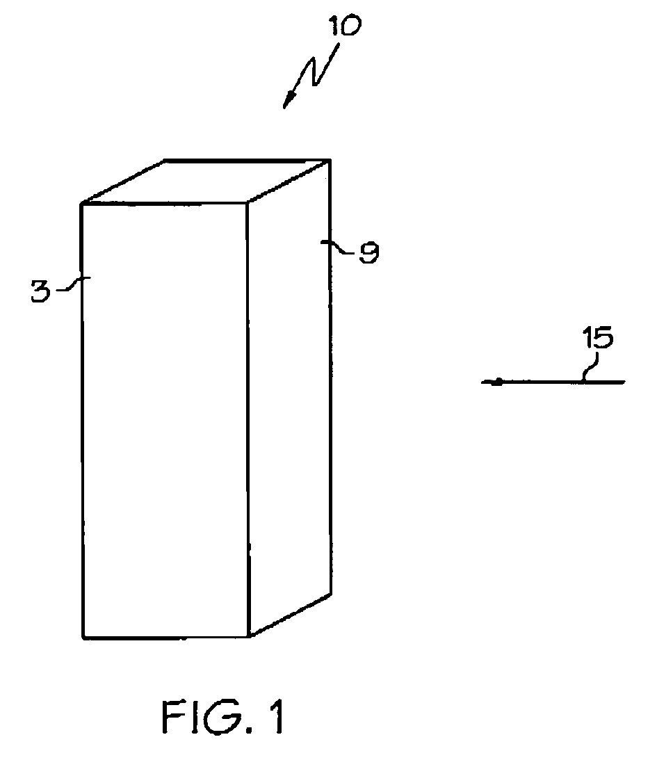
[0016]Referring to FIG. 1, a four-sided laser beam receiver 10 according to the present invention is shown receiving a rotating laser beam 15. Each of the four vertical sides 3, 5, 7, 9 of the receiver 10 has an array of photosensors. Each array includes a plurality of photosensors arranged in a vertical column. The four arrays of photosensors on the sides of the laser receiver 10 are identical. Each photosensor is connected electronically in parallel to the three photosensors at the same height on the three other sides of the receiver 10. The photosensors can be photocells, phototransistors, photodiodes, or PIN diodes, but are typically silicon photodiodes or PIN diodes. The four identical arrays of photosensors are arranged on the four sides of the receiver 10 to detect the rotating laser beam regardless of the direction from which it comes to the receiver 10.

[0017]Referring to FIGS. 2A–B, a schematic circuit diagram of a single array 20 of photosensors is illustrated. The photose...


PUM


Abstract

A laser beam receiver with non-interdigitated photosensors arranged in a repeating pattern of “n” channels of photosensors in each of “m” sectors is disclosed. The photocurrent from both the anode and cathode terminals of the photosensor is used to determine laser beam position. The repeating patterns connect one set of “n” channel amplifier channels with the corresponding set of “m” sector amplifier channels. The position of the laser beam is determined by its position relative to the sector and channel the laser beam impinges on. The laser beam position relative to sector boundaries is determined by the distribution of photosensor current into the “n” channels of amplifiers from the “n” photosensors within each sector. The sector of the photosensor the laser beam impinges on is determined by the distribution of photosensor current into the “m” channels of sector amplifiers from the “m” groups of “n” photosensors.

Description

BACKGROUND OF THE INVENTION[0001]The present invention generally relates to a laser beam receiver circuit and, in particular, relates to a photosensitive receiver circuit that determines the position of a laser beam from the sector and the channel of the photosensitive array impinged on by the laser beam.[0002]Rotating laser beams and laser beam receivers are commonly used in agriculture, construction, civil engineering, machine control or surveying applications to obtain positional information about a rotating reference plane of light. Conventionally, positional information is found by sweeping a rotating laser beam over the full length of a long array of photosensors. When the rotating laser beam impinges on one of the photosensors, a signal is provided by the illuminated photosensor which is processed by appropriate circuitry and used to control an operator display or used as an input to machine control circuitry.[0003]Many surveying and engineering applications using laser beam ...

Claims


Application Information

Patent Timeline
Patent Type & Authority Patents(United States)
IPC IPC(8): G01C3/08G01C15/00H01L27/14
CPCG01C15/006
Inventor DOUGLAS, FRANK BEARD
Owner TRIMBLE NAVIGATION LTD
Features
  • R&D
  • Intellectual Property
  • Life Sciences
  • Materials
  • Tech Scout
  • Unparalleled Data Quality
  • Higher Quality Content
  • 60% Fewer Hallucinations
Learn More