Real-time radiation sensor calibration

a real-time radiation and sensor technology, applied in the field of real-time radiation sensor calibration, can solve the problems of difficulty in separating signals, and various undesirable components in detector output signals

Inactive Publication Date: 2006-04-18
BAE SYST INFORMATION & ELECTRONICS SYST INTERGRATION INC
View PDF107 Cites 48 Cited by
  • Summary
  • Abstract
  • Description
  • Claims
  • Application Information

AI Technical Summary

Problems solved by technology

One issue in connection with at least some types of radiation detectors is that often it may be challenging to separate those signals output by the detector that are actually due to radiation of interest incident to the detector from various undesirable components which may be present in the detector output signals.
For example, detector output signals may include various undesirable components due to variations in temperature of the detector itself that are not necessarily due to the radiation of interest.
In particular, temperature changes in the vicinity of the detector that may affect the temperature of the detector, sometimes referred to as ambient temperature variations (e.g., changes in temperature of a substrate on which the detector is fabricated, changes in temperature of a package in which the detector is housed, average temperature changes in a scene of interest itself), in turn may cause undesirable components to be present in the detector output signals.
In some cases, these undesirable components may be hundreds of times larger than the instantaneous signals resulting from the radiation of interest, thereby detrimentally reducing the dynamic range of the detector and / or processing circuitry associated with the detector with respect to the radiation of interest.
In particular, with respect to conventional thermal imaging systems, it is generally thought to be impractical to operate such systems without active stabilization of the temperature of the detectors.
Depending on the difference between the predetermined stabilization temperature and the actual ambient temperature in the vicinity of the detectors, the TE cooler may consume appreciable power resources of the imaging system.

Method used


Image

  • Real-time radiation sensor calibration
  • Real-time radiation sensor calibration
  • Real-time radiation sensor calibration

Examples


Embodiment Construction

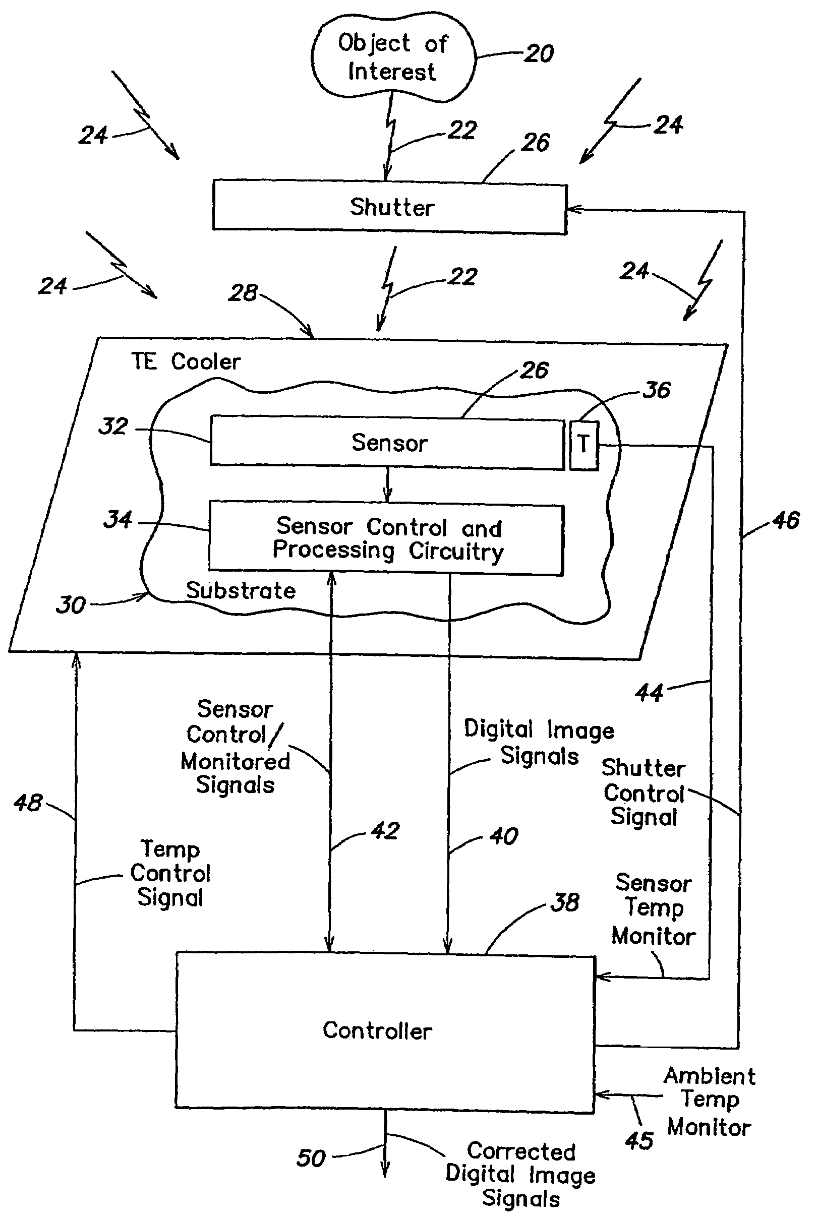
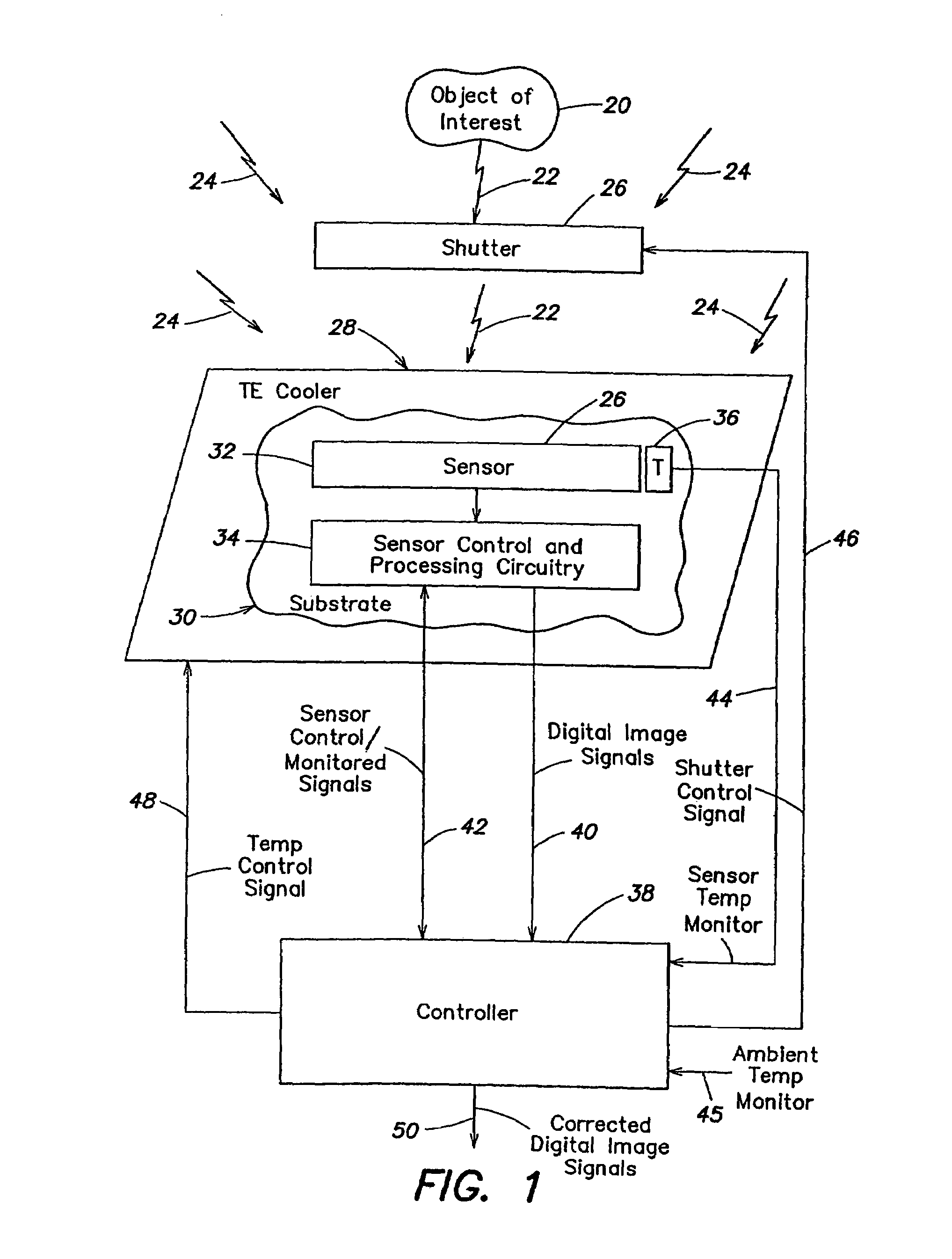
[0028]As discussed above, a radiation sensor outputs signals based on radiation that impinges on the sensor. Such a sensor may be used in an imaging system that produces images (e.g., on a display) based on radiation incident to the sensor from a scene of interest. The sensor output signals, however, may contain significant undesirable components due in part to changes in temperature of the sensor itself that are not necessarily due to the radiation of interest. In some cases, these undesirable signal components may be hundreds of times larger than the instantaneous signals resulting from the radiation of interest in the scene being imaged, thereby detrimentally reducing the dynamic range of the sensor and / or processing circuitry associated with the sensor with respect to the radiation of interest.

[0029]With respect to undesirable signal components, changes in temperature of the sensor that are not related to the radiation of interest may have an average effect over time (i.e., a DC...


PUM


Abstract

One embodiment of the invention is directed to methods and apparatus for determining a variation of a calibration parameter of a pixel of the thermal sensor during operation of the imaging apparatus, after an initial calibration procedure. Another embodiment of the invention is directed to methods and apparatus for calculating a gain calibration parameter using first and second ambient temperature values and respective first and second resistance values for a pixel of a sensor. A further embodiment of the invention is directed to calculating an offset calibration parameter for at least one pixel using a gain of the at least one pixel between first and second times and an ambient temperature at a third time, wherein the pixel is exposed to both scene and ambient radiation at the third time.

Description

BACKGROUND OF THE INVENTION[0001]1. Field of the Invention[0002]The present invention generally relates to radiation sensors, and in particular, to compensating operating parameters and / or output signals of radiation sensors for changes in temperature of the sensors.[0003]2. Discussion of the Related Art[0004]A radiation detector is a device that produces an output signal which is a function of an amount of radiation that is incident upon an active region of the radiation detector. Radiation detectors may be designed and constructed to be sensitive to particular regions of the electromagnetic spectrum. For example, infrared detectors are radiation detectors that are sensitive to radiation in the infrared region of the electromagnetic spectrum. One example of an infrared detector includes a thermal detector, which detects radiation based upon a change in the temperature of an active region of the detector due to absorption of radiation incident to the detector.[0005]A variety of imag...

Claims


Application Information

Patent Timeline
Patent Type & Authority Patents(United States)
IPC IPC(8): G01J5/00H01L25/00G01J5/06H01L27/146
CPCG01J5/06H04N5/3655H04N5/33H01L27/146G01J2005/068G01J5/064G01J5/80H04N25/671H04N25/673
Inventor ALLEN, THOMAS P.BUTLER, NEAL R.
Owner BAE SYST INFORMATION & ELECTRONICS SYST INTERGRATION INC
Why Eureka
Try Eureka