Quick attachment fixture and power card for diode-based light devices

a technology of power card and diode, which is applied in the direction of coupling device connection, optical radiation measurement, instruments, etc., can solve the problem of time-consuming and labor-intensive process of securely placing led devices into testing positions with conventional fixtures

Inactive Publication Date: 2006-04-18
HONEYWELL INT INC
View PDF17 Cites 30 Cited by
  • Summary
  • Abstract
  • Description
  • Claims
  • Application Information

AI Technical Summary

Benefits of technology

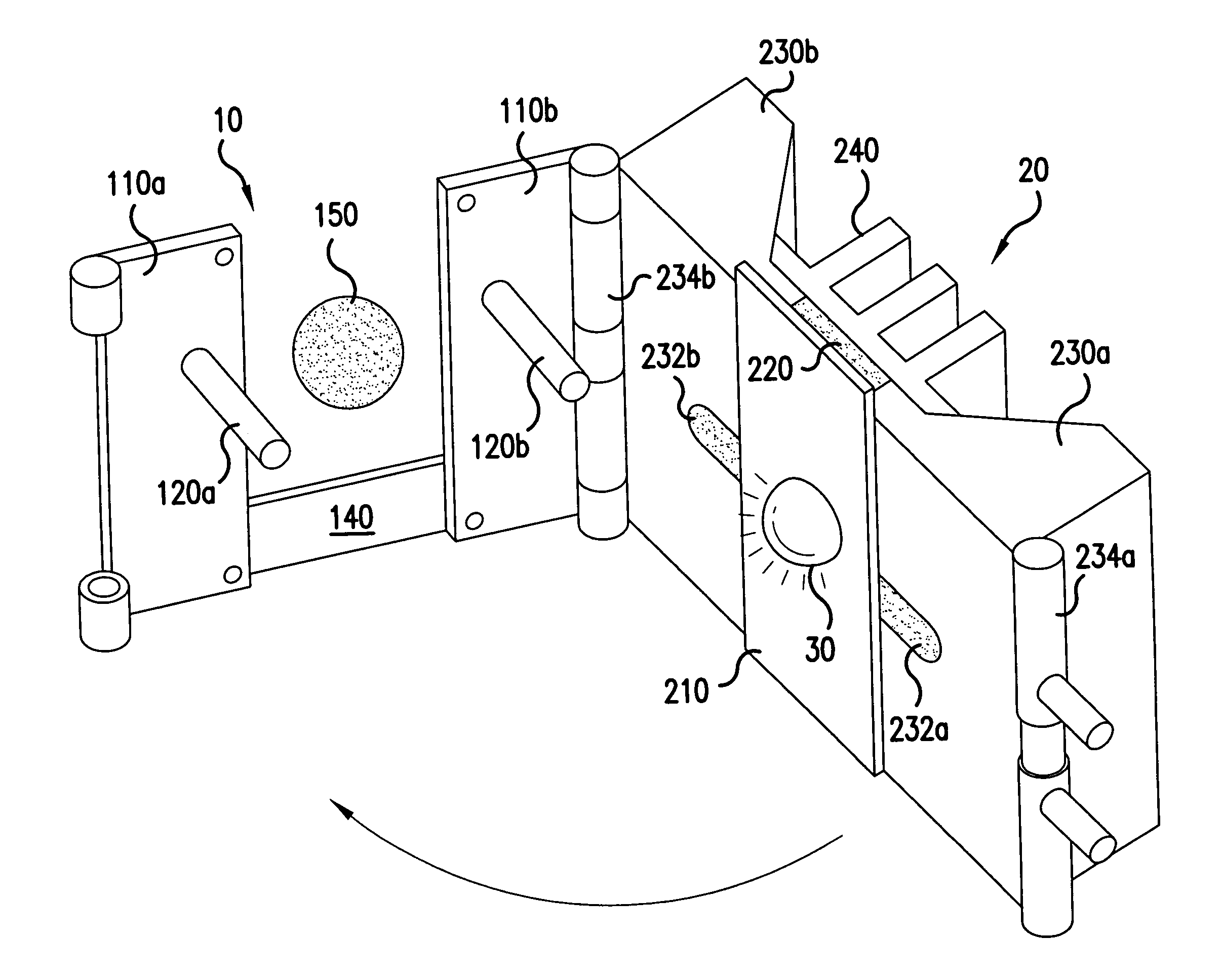
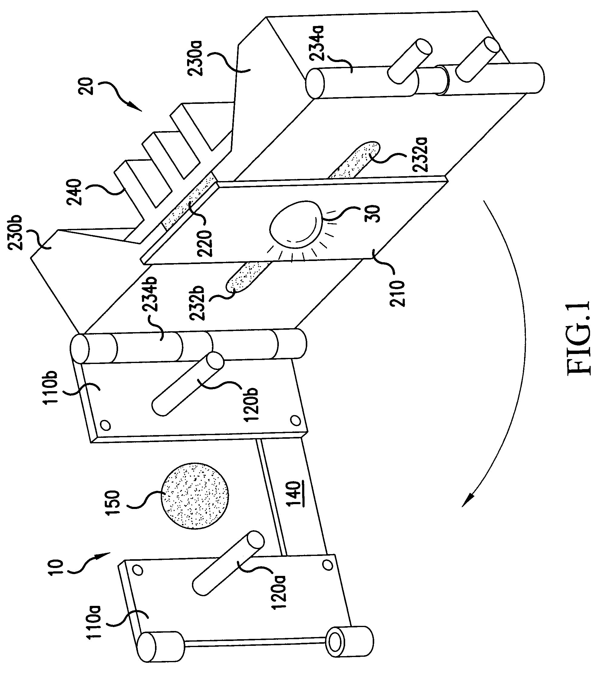
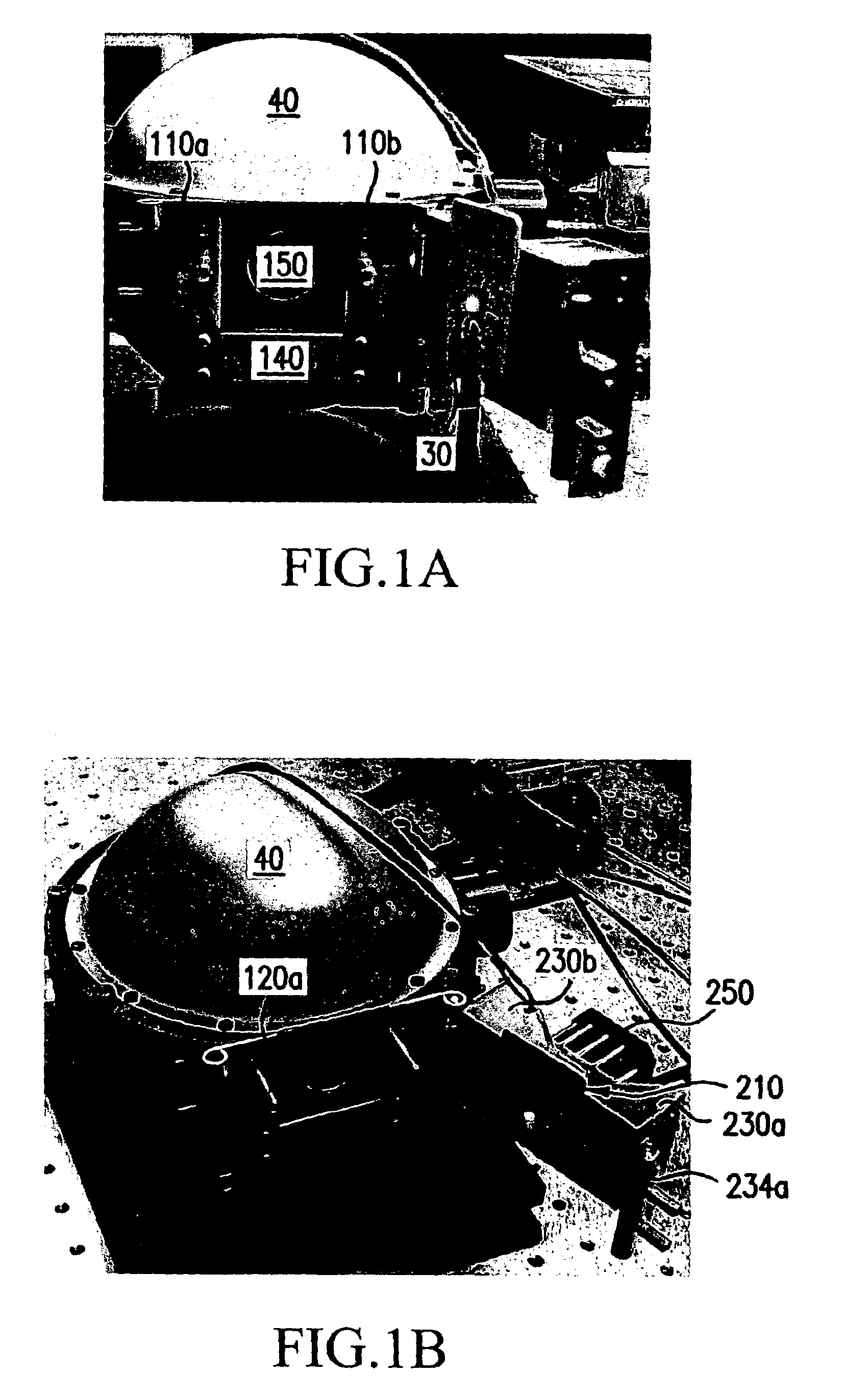
[0007]Exemplary embodiments of the present invention utilize quick disconnect fixtures capable of securely fixing each of a plurality of diode light sources into position for repeatable testing, while providing thermo-electric cooling (TEC) for maintaining each of the tested diode light sources at a constant emitter junction temperature.
[0012]In an exemplary embodiment, the quick attachment module includes another fastener, e.g., a second quick disconnect hinge, to be engaged with a fastening mechanism on the mounting assembly when the diode light sources are moved into fasting position. Based on the LT fit connection between the two locating pins and the thermally insulating module, exemplary embodiments of the present invention need only two fasteners (or quick disconnect hinges) to securely and accurately place each diode light source in testing position when repeatable testing is being performed for a large number of diode light sources. When modular wear blocks (e.g., made of plastic) are used in the thermally insulating module, any eventual loosening of the LT fit can be eliminated by merely replacing these modular wear blocks.
[0013]According to an exemplary embodiment, the mounting assembly may include a low-conductive plate, which becomes positioned between the mounting plate and the quick attachment module when a diode light source is moved into testing position. For example, a low-conductive plate may be fastened to the mounting plate of the mounting assembly. A low-conductance material (e.g., semiconductor material) may cover up electrical pathways to the diode light source that provide power during testing. Thus, when the quick attachment module is comprised of a metallic or other electrically conductive material, the low-conductive plate may help prevent short circuiting or electric shocks during testing.

Problems solved by technology

However, while conducting repeated testing on a large number of LED devices, the process of securely placing each LED device into testing position with conventional fixtures is very time consuming.
Also, another problem exists in that a constant emitter junction temperature must be maintained for each of the LED devices being tested in order to obtain accurate results.

Method used


Image

  • Quick attachment fixture and power card for diode-based light devices
  • Quick attachment fixture and power card for diode-based light devices
  • Quick attachment fixture and power card for diode-based light devices

Examples


Embodiment Construction

[0025]Exemplary embodiments of the present invention are disclosed in the following description.

[0026]The present invention is directed to a device for fixating diode light sources to a specific testing position relative to measurement devices. According to exemplary embodiments, the device has a quick disconnect configuration that allows for the repeated testing of a high number of diode light sources. Furthermore, this fixture device is operable to adjust a junction temperature of each diode light source in order to maintain a constant temperature for all of the light sources being tested.

[0027]Exemplary embodiments of the present invention allow for each of the plurality of diode light sources to be quickly attached to the fixture device and moved into testing position. Thus, the fixture device will hereinafter be referred to a “quick attachment device.” However, this term is used for purposes of description only and should not be construed as limiting the present invention in an...


PUM


Abstract

A quick attachment device for use in the repeated testing of diode light sources (30) includes a quick attachment module (10) having a fixed location with respect to a testing position (150) for the diodes (30), and a mounting assembly (20) on which each diode (30) is mounted during testing. The quick attachment module (10) includes a quick disconnect fastener and two locating pins (120a and 120b) for securing the mounting assembly (20) for testing, where the two locating pins (120a and 120b) have a locational transition fit connection with the mounting assembly (20). The mounting assembly (20) may further include a thermal-electric cooling device (260) for cooling the diode light sources (30) during testing.

Description

FIELD OF THE INVENTION[0001]The present invention is directed to diode-based light devices, and more particularly, to quick attachment testing and power connections for diode-based light devices.BACKGROUND OF THE INVENTION[0002]A variety of light-emitting devices exist that utilize diode-based light sources. For example, such devices utilize light emitting diodes (LEDs) that are configured to emit visible light, infrared (IR) diodes for emitting IR light, and ultraviolet (UV) diodes for emitting UV light.[0003]In light devices that utilize a diode-based light source, the diode may include pins that are connected to electrical wiring for providing power to the diode. Other devices use surface-mounted diodes, in which each diode is affixed to a mounting plate that includes solder pads. Electrical power connections may be soldered onto these pads to provide the LED power. Examples of such surface-mounted LEDs include the LUXEON™ Star LED module and the LUXEON Star / O LED module, which a...

Claims


Application Information

Patent Timeline
Patent Type & Authority Patents(United States)
IPC IPC(8): G01R31/26G01R1/04G01R31/44
CPCG01R1/0416G01R31/2635G01J1/0223G01J1/0271G01R31/44G01J2001/4247G01J2001/0481
Inventor BUTSCH, STEVE M.SINGER, JEFFREY M.MACHI, NICOLO F.
Owner HONEYWELL INT INC
Why Eureka
Try Eureka